Grinding apparatus for buttons on rock drill bit

a drilling bit and button technology, applied in the direction of boring/drilling apparatus, grinding machines, other manufacturing equipment/tools, etc., can solve the problems of not allowing a grinding pressure equal to zero, regrinding the button off center from its longitudinal axis, vibration and noise, etc., to achieve the ability of the grinding apparatus to meet future demands, and the flexibility of the machin

Active Publication Date: 2008-07-22
C M E BLASTING & MINING EQUIP
View PDF11 Cites 18 Cited by
  • Summary
  • Abstract
  • Description
  • Claims
  • Application Information

AI Technical Summary

Benefits of technology

[0009]It is a further object of the present invention to provide grinding apparatus with a grinding machine that utilizes an electric motor capable of producing high torque over a range of RPMs, with a relatively compact size and weight.
[0011]It is a further object of the present invention to provide grinding apparatus having a frequency inverter to optimize the power and / or torque to size ratio in a grinding machine, and to add the flexibility to change the motor performance characteristics as deemed appropriate for optimized grinder performance.
[0016]The benefit of the electronic programmable control system and its various built in capabilities is that the range of RPMs for example is upgradable and / or adjustable to meed future demands. For example, with the configuration of the present invention it would be rpossible to change the overall range of RPMs to 1000 to 11000 RPMs if for example a new grinding cup matrix and / or new overall configuration were developed. Another potential reason that the operating characteristics may need to be modified would be if the material in the button being ground changed. Due to the inherent flexibility of the overall control system and components / modules connected to it the ability for the grinding apparatus to meet future demands is maximized.

Problems solved by technology

On buttons where wear is uneven, typically gauge buttons, this may result in regrinding the button off center from its longitudinal axis.
This, for example, does not allow for a grinding pressure equal to zero.
Longstanding problems with these types of grinding machines are vibration and noise due to high rotational speeds, wear, the requirement for large compressors for pneumatic systems and long grinding times per button, in the larger sizes of six minutes or more.

Method used


Image

  • Grinding apparatus for buttons on rock drill bit
  • Grinding apparatus for buttons on rock drill bit
  • Grinding apparatus for buttons on rock drill bit

Examples


Embodiment Construction

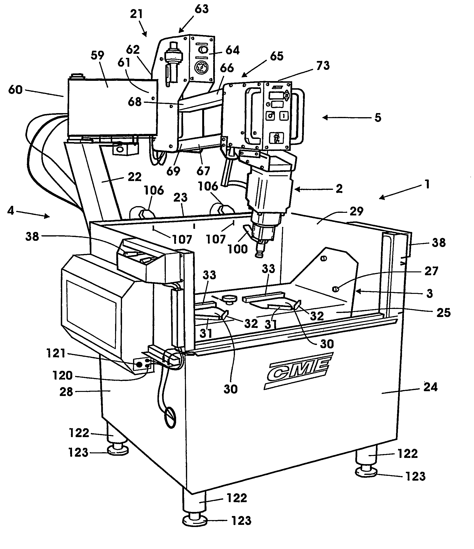
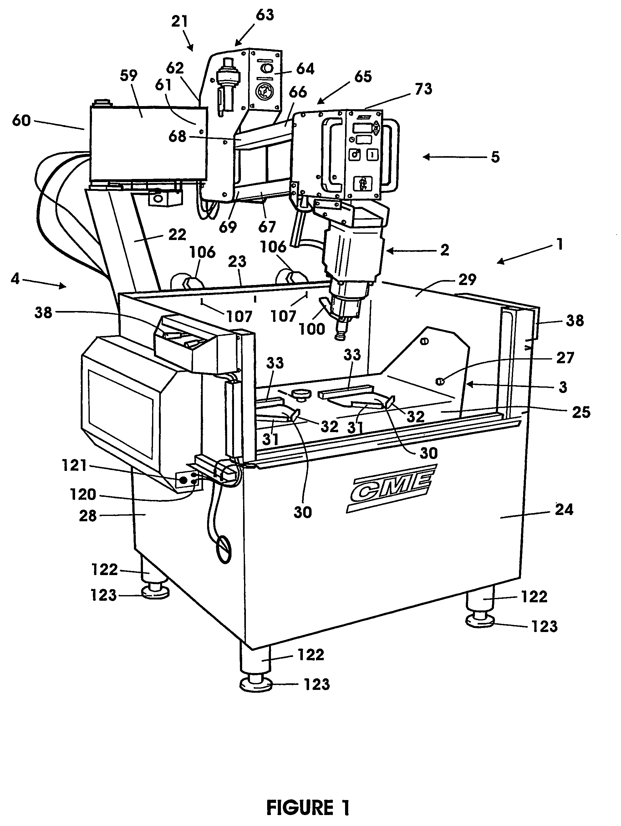
[0039]With reference to FIGS. 1, 3 and 4 one embodiment of a grinding apparatus according to the present invention is generally indicated at 1. The grinding apparatus 1 includes a grinding machine 2, means for holding one or more bits to be ground generally indicated at 3 and a support system generally indicated at 4. The grinding machine 2, means for holding the bits 3 and support system 4 are arranged to permit relative movement been the grinding machine 2 and the bit to be ground to permit alignment of the grinding machine 2 with the longitudinal axis of the buttons on the bit. The grinding apparatus 1 preferably has a control system having a programmable operator control panel 5 capable of monitoring and adjusting one or more operational parameters. The operational parameters of most interest are selected from the group consisting of feed pressure, grinding cup RPM and grinding time. The control system is preferably capable of monitoring and adjusting one or more additional oper...


PUM

PropertyMeasurementUnit
diameteraaaaaaaaaa
frequencyaaaaaaaaaa
frequencyaaaaaaaaaa

Abstract

The present invention relates to grinding apparatus for grinding the hard metal inserts of rock drill bits, said grinding apparatus having a grinding machine carried on an support system that provides a feed pressure for said grinding machine during grinding, said grinding machine equipped with a grinding pin driven by motor to rotate about its longitudinal axis wherein the grinding cup is rotated at variable speeds and the support system provides a variable feed pressure.

Description

PRIOR APPLICATION[0001]This application is a U.S. national phase application based on International Application No. PCT / CA2004 / 000222, filed 19 Feb. 2004, claiming priority from Canadian Patent Application No. 2,419,214, filed 19 Feb. 2003.FIELD OF THE INVENTION[0002]The present invention relates to improvements in apparatus for grinding the hard metal inserts or working tips of rock drill bits (percussive or rotary), tunnel boring machine cutters (TBM) and raised bore machine cutters (RBM) and more specifically, but not exclusively, for grinding the cutting teeth or buttons of a rock drill bit or cutter.BACKGROUND OF THE INVENTION[0003]In drilling operations the cutting teeth (buttons) on the drill bits or cutters become flattened (worn) after continued use. Regular maintenance of the drill bit or cutter by regrinding (sharpening) the buttons to restore them to substantially their original profile enhances the bit / cutter life, speeds up drilling and reduces drilling costs. Regrindi...

Claims


Application Information

Patent Timeline
Patent Type & Authority Patents(United States)
IPC IPC(8): B24B49/00B24B3/33B24B27/04
CPCB24B27/04B24B3/33
Inventor SJOLANDER, BJORNSJOLANDER, BO THOMASSJOLANDER, ROBERT
Owner C M E BLASTING & MINING EQUIP
Why Eureka
Try Eureka