Minute high-performance rare earth magnet for micromini product and process for producing the same

a rare earth permanent magnet, micro-mini technology, applied in the direction of superimposed coating process, liquid/solution decomposition chemical coating, magnetic body, etc., can solve the problems of difficult to recover magnetic properties, long time-consuming and laborious, solution remains in the pores of sintered magnets, etc., to achieve small and high output power motor, small and high performance magnets, and sufficient restoration of magnetic properties

Inactive Publication Date: 2008-07-22
JAPAN SCI & TECH CORP +3
View PDF18 Cites 18 Cited by
  • Summary
  • Abstract
  • Description
  • Claims
  • Application Information

AI Technical Summary

Benefits of technology

[0030]According to the methods of the present invention, by depositing and diffusing a rare earth metal on a magnet surface damaged and denatured by mechanical working, a phase rich in the rare earth metal such as Nd on a surface of the d

Problems solved by technology

In the method described in the patent document 1, there are the problems that since the denatured layer is assumed to extend 10 μm deep or more, the polishing takes a long time; rapid polishing generates a denatured layer a new; and furthermore, when the chemical polishing is applied, an acid solution remains in pores of the sintered magnet and tends to generate corrosion marks.
Furthermore, according to the method described in the patent document 3, since the deposition alone does not cause a metallic reaction to the Nd2Fe14B phase and the Nd-rich phase, it is difficult to recover the magnetic properties.
Still furthermore, when Sm is diffused inside of the magnet by the heat treatment, since

Method used


Image

  • Minute high-performance rare earth magnet for micromini product and process for producing the same
  • Minute high-performance rare earth magnet for micromini product and process for producing the same
  • Minute high-performance rare earth magnet for micromini product and process for producing the same

Examples


embodiment 1

[0055]From an alloy ingot having a composition of Nd12.5Fe78.5Co1B8, alloy foil having a thickness of from 0.2 to 0.3 mm was prepared according to the strip casting method. Next, the foil was packed in a vessel and allowed to absorb hydrogen gas at 500 kPa and at room temperature and the gas was released, thereby obtaining un even powder having a general size from 0.15 to 0.2 mm. Then, the uneven powder was subjected to jet mill pulverization, and thereby fine powder of approximately 3 μm particle size was prepared.

[0056]The fine powder was admixed with 0.05% by weight of calcium stearate, press-molded in a magnetic field, charged into a vacuum furnace and sintered at 1080 degree centigrade for 1 hr, and thereby a cubic magnet block material with sides of length 18 mm was obtained.

[0057]Subsequently, to the cubic magnet block material, grind stone cutting, outer periphery grinding and ultrasonic drilling were applied and thereby a cylindrical magnet having an outer diameter of 1 mm,...

embodiment 2

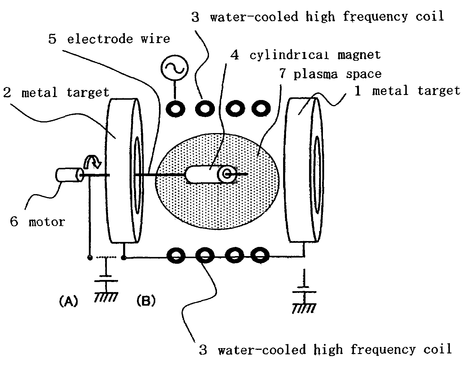
[0066]On the cylindrical magnets that were manufactured in embodiment 1 and have an outer diameter of 1 mm, an inner diameter of 0.3 mm and a length of 3 mm, metals of Nd, Dy, Pr, Tb and Al each were deposited, respectively. Here, target dimensions of Nd and Al were 80 mm in the outer diameter, 30 mm in the inner diameter and 20 mm in the thickness, the same as that of Dy in embodiment 1; on the other hand, Pr and Tb targets were prepared by applying and fixing the respective metals with a thickness of 2 mm on the surfaces that faced to the magnet of the Al target.

[0067]After the Nd metal target was attached to the three-dimensional sputtering apparatus, two of the cylindrical magnets were attached to a tungsten electrode wire followed by depositing the Nd metal. Similarly, other metals were deposited on the surface of the magnets. In the deposition, into the apparatus, Ar gas was introduced to maintain a pressure inside of the apparatus at 3 Pa, RF output power of 20 W and DC outpu...

embodiment 3

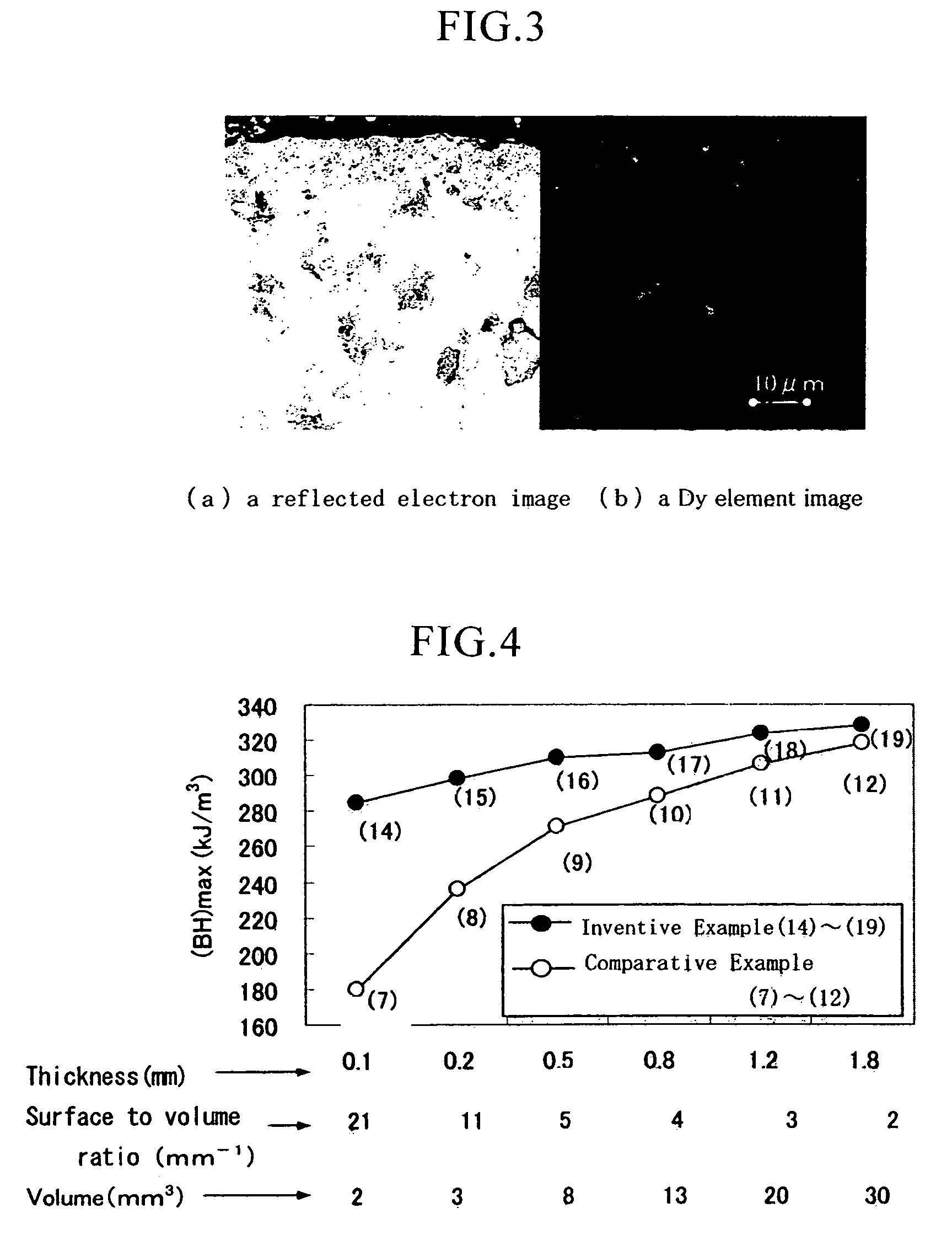
[0071]A sintered magnet block having a composition of Nd12Dy2.5Fe76.5Co1B8 was cut, ground and drilled, and thereby a disc-like magnet having an outer diameter of 10 mm, an inner diameter of 3 mm and a length of 1.4 mm was prepared. Volume is 100 mm3, surface area is 200 mm2, and surface area to volume ratio is 2.0 mm−1. On both surfaces thereof, a Tb film was deposited. The sputtering conditions were as follows. That is, by applying RF output of 40 W and DC output of 2 W, the reverse sputtering was performed for 10 min; thereafter by applying RF output of 150 W and by varying DC output from 100 to 800 W, magnets different in sputtering conditions were prepared.

[0072]The relationship between the DC output and the film thickness of the deposited Tb film was investigated. Based on the result of investigation, in order to obtain a thickness of a deposited Tb film of substantially 3 μm for all magnets, the sputtering time was set to be 20 min for 100 W and to be 5 min for 800 W. Further...


PUM

PropertyMeasurementUnit
Pressureaaaaaaaaaa
Fractionaaaaaaaaaa
Concentrationaaaaaaaaaa

Abstract

A method of manufacturing a rare earth permanent magnet comprises the steps of: forming a rare earth magnet by applying mechanical processing to a magnet block material, thereby damaging the surface of the magnet and causing a magnetic characteristic (BH)max of the magnet to deteriorate, followed by transforming a rare earth metal or an alloy thereof into fine particles or a vapor, and allowing the fine particles or vapor to diffuse and permeate the magnet, thereby improving the quality of the damaged magnet surface portion so that the magnetic characteristic (BH)max is recovered.

Description

CROSS-REFERENCE TO RELATED APPLICATIONS[0001]This application is a 35 U.S.C. 371 national stage filing of International Application No. PCT / JP2004 / 002738, filed on Mar. 4, 2004, which claims priority to Japanese Patent Application No. 2003-096866, filed on March 31, 2003 in Japan.TECHNICAL FIELD OF THE INVENTION[0002]The present invention relates to a rare earth permanent magnet such as an Nd—Fe—B system or Pr—Fe—B system, in particular, a small and high performance rare earth permanent magnet for micro applications such as micro motors and so on, and a method of manufacturing the same.BACKGROUND OF THE INVENTION[0003]An Nd—Fe—B rare earth sintered magnet is known as the permanent magnet with the best performance, widely used in voice coil motors (VCMs) of hard disc drives, magnetic circuits for magnetic resonance imaging devices (MRIs) and so on. Furthermore, it is known that in the magnet, the internal structure has a microstructure in which a periphery of an Nd2Fe14B primary phas...

Claims


Application Information

Patent Timeline
IPC IPC(8): C23C14/34H01F1/057H01F41/02
CPCC23C14/3464C23C14/3471H01F41/0293H01F1/0577H01F41/0253H01F1/057
Inventor MACHIDA, KENICHISUZUKI, SHUNJISAKAGUCHI, EIJIISHIGAKI, NAOYUKI
Owner JAPAN SCI & TECH CORP
Why Eureka
Try Eureka