Component parts joining structure

a technology of joining structure and component parts, applied in the direction of coupling device connection, liquid fuel engine components, vehicle seats, etc., can solve the problems of inefficiency of the mounting work required for the plate mounting structure, deformation or cracking of the upper surface of the head portion, etc., to facilitate the coupling of component parts and simplify the connecting activities of parts

Active Publication Date: 2008-08-12
MORIROKU
View PDF6 Cites 12 Cited by
  • Summary
  • Abstract
  • Description
  • Claims
  • Application Information

AI Technical Summary

Benefits of technology

[0009]The objective of the present invention is to provide a joining structure of component parts that facilitates the coupling of component parts and simplifies the connecting activities of parts.
[0010]Another objective of the present invention is to provide a joining structure of component parts that can fix a component part onto another part quickly.
[0022]In the joining structure of the present invention, the protruding portion formed on the side of a first component part takes the form of a hollow body that prevents bringing about sinking, deforming and cracking of the side surface of the first component part, even in the event that the protruding portion is enlarged in order to increase the strength for connecting the first component part and a second component part. In addition, the connecting groove formed on the side of the second component part is also defined by a hollow body that comprises a pair of supporting ribs and a supporting plate bridging the pair of supporting ribs. Consequently, the hollow body can prevent generating the defects of sinking, deforming and cracking in the side surface of the second component part, even in the event that the supporting ribs and the supporting plate are increased in thickness in order to enhance the rigidity of the coupling arrangement between the first and second component parts.
[0024]In addition, the first and second component parts can be joined by inserting a flange portion of the first component part into the connecting groove of the second component part only in one direction. Therefore, the parts can be joined quickly and easily.

Problems solved by technology

In the event that the hook is molded from a synthetic resin and the thickness of the junction is increased, however, there is the possibility that a recess or so-called sink, a deformation or a crack is produced in the upper surface of the head portion when the junction between the head and leg portions are cooled down.
Therefore, the plate mounting structure cannot be used in the state that the member having the hole appears on the outside.
Therefore, the mounting work required for the plate mounting structure is not always efficient.

Method used


Image

  • Component parts joining structure
  • Component parts joining structure
  • Component parts joining structure

Examples


embodiment 1

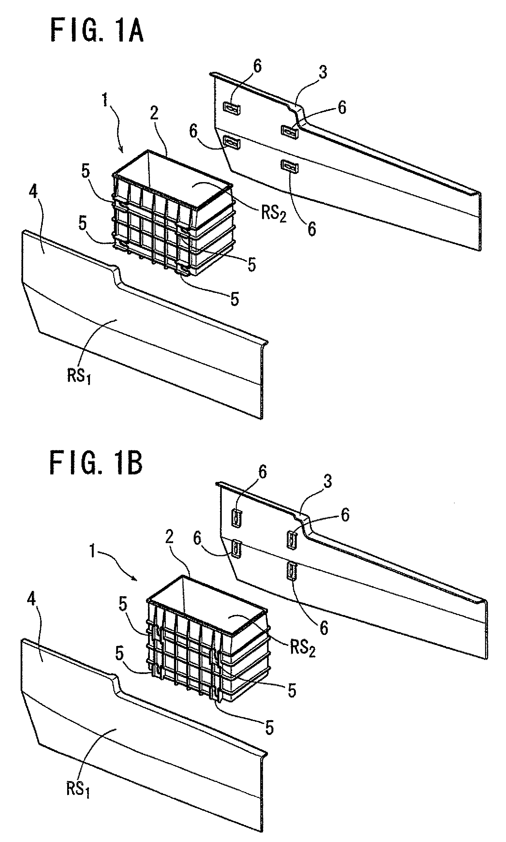
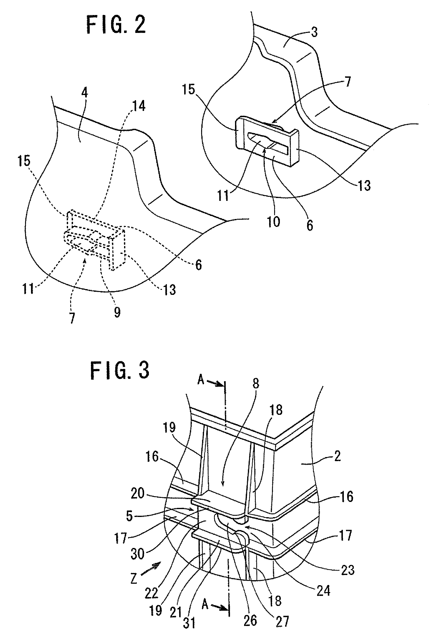
[0041]FIGS. 1 to 4 shows a first embodiment of the present invention. As is shown in FIG. 1A, a console assembly 1 is made up by connecting a right side panel 3 and a left side panel 4 to a console box 2 which is made to open at a top thereof. The box 2, the right side panel 3 and the left side panel 4 are integrally molded from a synthetic resin material, respectively. Four supporting portions 5 are formed integrally on each of left and right sides of the box 2. Four flange portions 6 are formed integrally on each of the left and right side panels 3, 4. These flange portions 6 are positioned in such a manner as to correspond to the supporting portions 5 on the box 2.

[0042]FIG. 1B shows a console assembly which is similar to that shown in FIG. 1A, and in FIG. 1B, constituent components given like reference numerals to those in FIG. 1A are constituent components having like designations. However, the console assembly 1 illustrated in FIG. 1B differs from that shown in FIG. 1A in that...

embodiment 2

[0054]FIGS. 5 to 7 show a second embodiment of the invention. In FIGS. 5 to 7, same reference numerals to those used in FIGS. 1 to 4 denote constituent components having the same designations as those described in FIGS. 1 to 4. The features of this embodiment resides in a configuration in which in place of the extension ribs 30, 31 in the first embodiment, a ridge portion 33 is formed in such a manner as to surround an opening 10 in a plate-shaped flange portion 6 formed at a connecting portion 7 of each of left and right side panels 3, 4, and distal end portions of the ridge portion 33 are made to continuously contact a rear end bent portion 13A of the flange portion 6. Since the rear end bent portion 13A is connected to the ridge portion 33, the rear end bent portion 13A has a portion which protrudes further downwards from an opening 10 side surface of the flange portion 6 than the rear end bent portion 13 of the first embodiment. In addition, a supporting portion 5 formed at a co...

embodiment 3

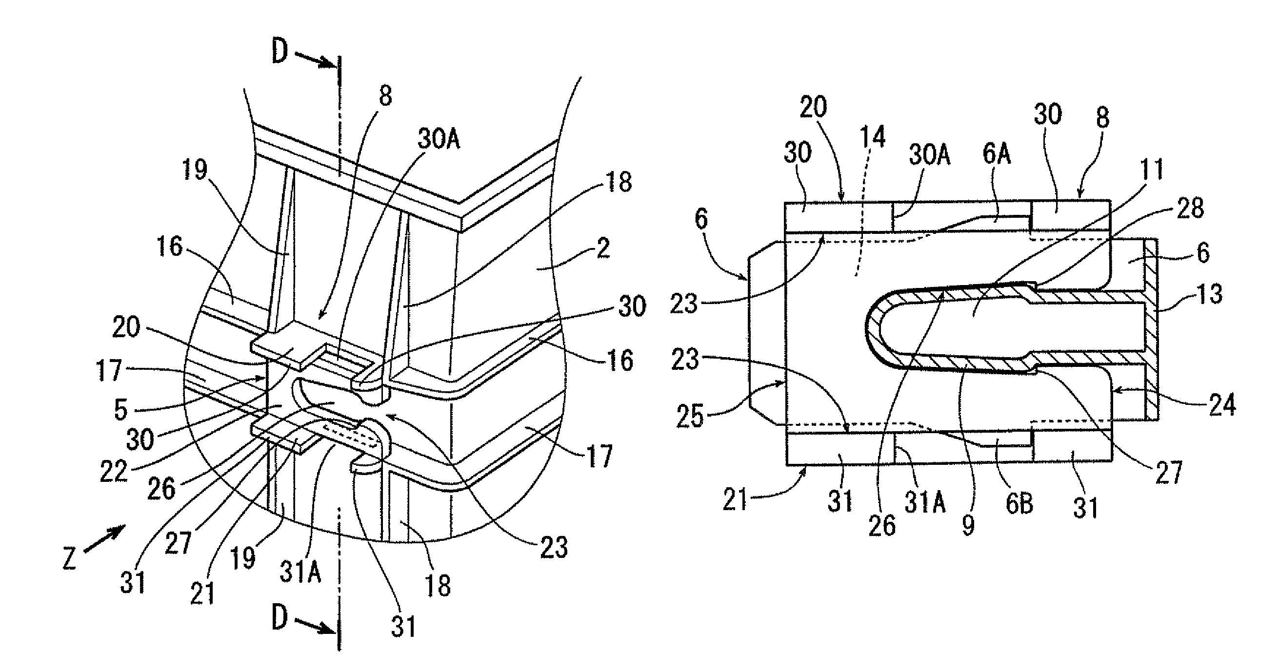
[0056]FIGS. 8 to 10 show a third embodiment. In FIGS. 8 to 10, same reference numerals to those used in FIGS. 1 to 4 denote constituent components having the same designations. The features of this embodiment resides in a configuration in which in place of the shoulder portion 28 of the protruding portion 9 and the step portion 27 of the upper slot 26, a pair of flange projections 6A, 6B are formed on a plate-shaped flange portion 6 and intermediate slots 30A, 31A are formed in supporting ribs 20, 21, respectively, in such a manner as to open to edge portions of extension ribs 30, 31, so that, when left and right side panels 3, 4 are connected to a box 2, the flange projections 6A, 6B are brought into engagement with the intermediate slots 30A, 31A, respectively, whereby connecting portions 7 of the left and right side panels 3, 4 can be prevented from being dislodged from connecting portions 8 of the box 2 in an ensured fashion. The other configurations are similar to those of the ...


PUM


Abstract

In a joining structure, a protruding portion on the side of a first component is a hollow body that prevents bringing about sinking, deforming, and cracking of the side surface of the first component part, even in the event that the protruding portion is enlarged in order to increase strength for connecting the first component part and a second component part. In addition, the connecting groove on the side of the second component part is also defined by a hollow body that includes a pair of supporting ribs and a supporting plate bridging the pair of supporting ribs. Consequently, the hollow body can prevent defects of sinking, deforming, and cracking in the side surface of the second component part, even in the event that the supporting ribs and the supporting plate are increased in thickness in order to enhance the rigidity of the coupling arrangement between the first and second component parts.

Description

BACKGROUND OF THE INVENTION[0001]1. Field of the Invention[0002]The present invention relates to a joining structure for fitting parts or articles together, in particular, for use in the process of assembling component parts, such as interior parts of vehicles.[0003]2. Description of the Related Art[0004]In the production line of vehicles, it is repeatedly performed by workers to attach various kinds of interior parts such as console boxes and door linings to vehicle bodies. Those parts have to be infallibly attached in the predetermined positions. In addition, it is desirable to simplify and facilitate the work of attachment of the parts and to shorten the amount of time required for attaching the parts, especially when those parts are attached to mass-produced cars.[0005]Japanese Patent Public Disclosure P2000-118318A discloses a structure for mounting a plate member on linings of a vehicle and a decorative component of a vehicle having the same structure. The plate mounting struc...

Claims


Application Information

Patent Timeline
Patent Type & Authority Patents(United States)
IPC IPC(8): B60R27/00B60R99/00
CPCF16B5/0664Y10T403/7062Y10T403/41Y10T403/64F16B2200/50
Inventor KOARAI, MANABU
Owner MORIROKU
Why Eureka
Try Eureka