
Spotting device for manufacturing DNA microarray and spotting method using the same

a technology of spotting device and microarray, which is applied in the field of spotting device spotting method using the same, can solve the problems of high degree of skill, time-consuming, expensive, and inability to analyze a large number of genes, and achieve the effect of reducing the time for manufacturing dna microarray

Inactive Publication Date: 2008-08-26
SAMSUNG ELECTRONICS CO LTD
View PDF12 Cites 2 Cited by
  • Summary
  • Abstract
  • Description
  • Claims
  • Application Information

AI Technical Summary

Benefits of technology

The device produces uniformly shaped spots, minimizes temperature effects on biomolecules, and significantly reduces the time required for manufacturing DNA microarrays by efficiently managing and depositing biomolecule solutions.

Problems solved by technology

Though a method of Sanger which had been used to analyze a base sequence until that time was steadily progressed by the development of a polymerase chain reaction (PCR) replicating DNA and automation thereof, it could not analyze a large number of genes since an analyzing process was complicated, time consuming, expensive, and high degree of skills were required.
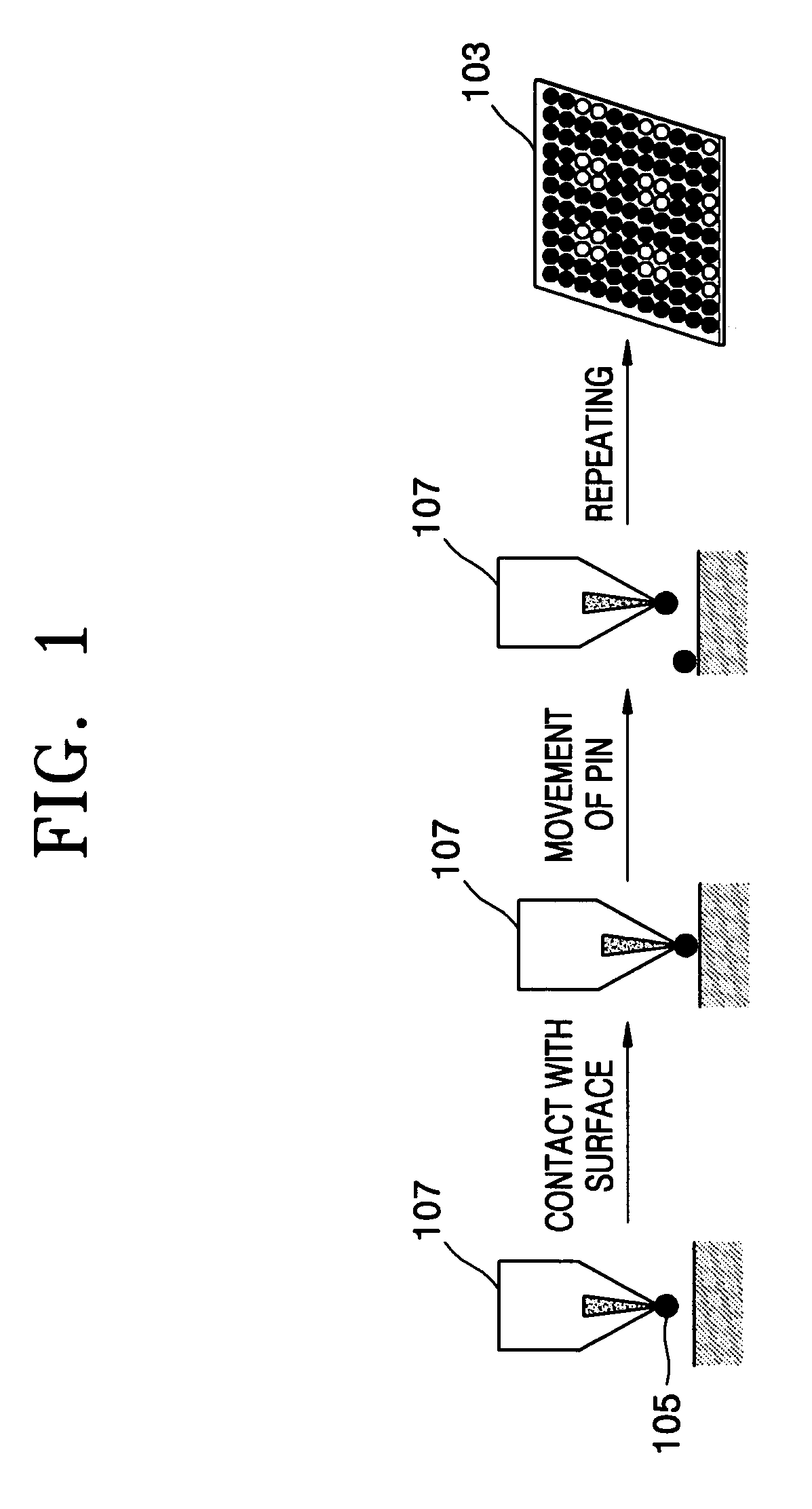
Also, the sizes of spots are not uniform, the pin is occasionally clogged, life time of the pin is not long, the concentration of the biomolecule solution is varied according to spotting time, and long time is required for spotting the biomolecule solution.
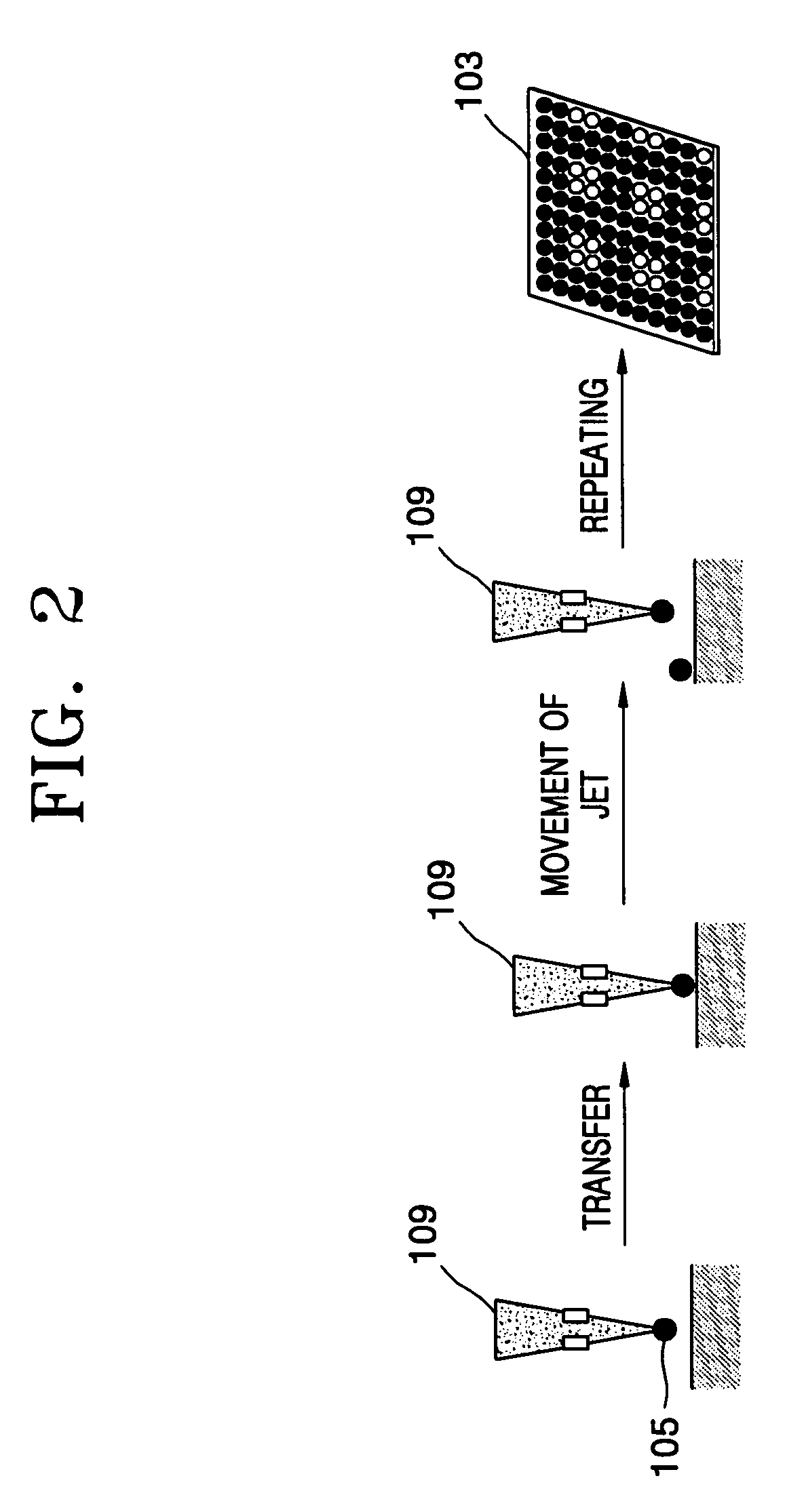
In the case of using inkjet, a bubble jet method momentarily requires ultrahigh heat, and thus, a part of the biomolecules which are sensitive to heat may be affected by the heat.
Also, a nozzle is occasionally clogged.

Method used


Image

  • Spotting device for manufacturing DNA microarray and spotting method using the same
  • Spotting device for manufacturing DNA microarray and spotting method using the same
  • Spotting device for manufacturing DNA microarray and spotting method using the same

Examples


examples

[0042]Conditions of a spotting experiment were as follows.

[0043]First, probe DNA oligomers were prepared. In FIG. 5B, perfectly matched probe DNA oligomers (WP MODY3 EXON 3-6, C6NH2-5′-CGGAGGAACCGTTTC-3′) were assigned to 1, 2, 5, 6, 9, 10, 13, and 14, and mismatched probe DNA oligomers (MP MODY EXON 3-6, C6NH2-5′-CGGAGGAACCATTTC-3′) were assigned to 3, 4, 7, 8, 11, 12, 15, and 16.

[0044]Then, 100 uM of the DNA oligomer, 100 uM of PEG, 3 uM of Cy5 activate ester, and a DMSO solution were prepared.

[0045]Next, droplets were formed using a spotting device for manufacturing a DNA microarray according to an embodiment of the present invention, frozen at −20° C., and then, subjected to a hybridization using 50 μM Mody3 Exon 3 as a target DNA. At this time, hybridization time was 16 hours and hybridization temperature was 32° C.

[0046]After washing, the resultant was scanned using PMT 573 (Scanner GenePix 4000B, Axon instruments, Inc.) at a wavelength of 532 nm in a greenmode.

[0047]FIG. 6A i...


PUM

PropertyMeasurementUnit
temperatureaaaaaaaaaa
diameteraaaaaaaaaa

Abstract

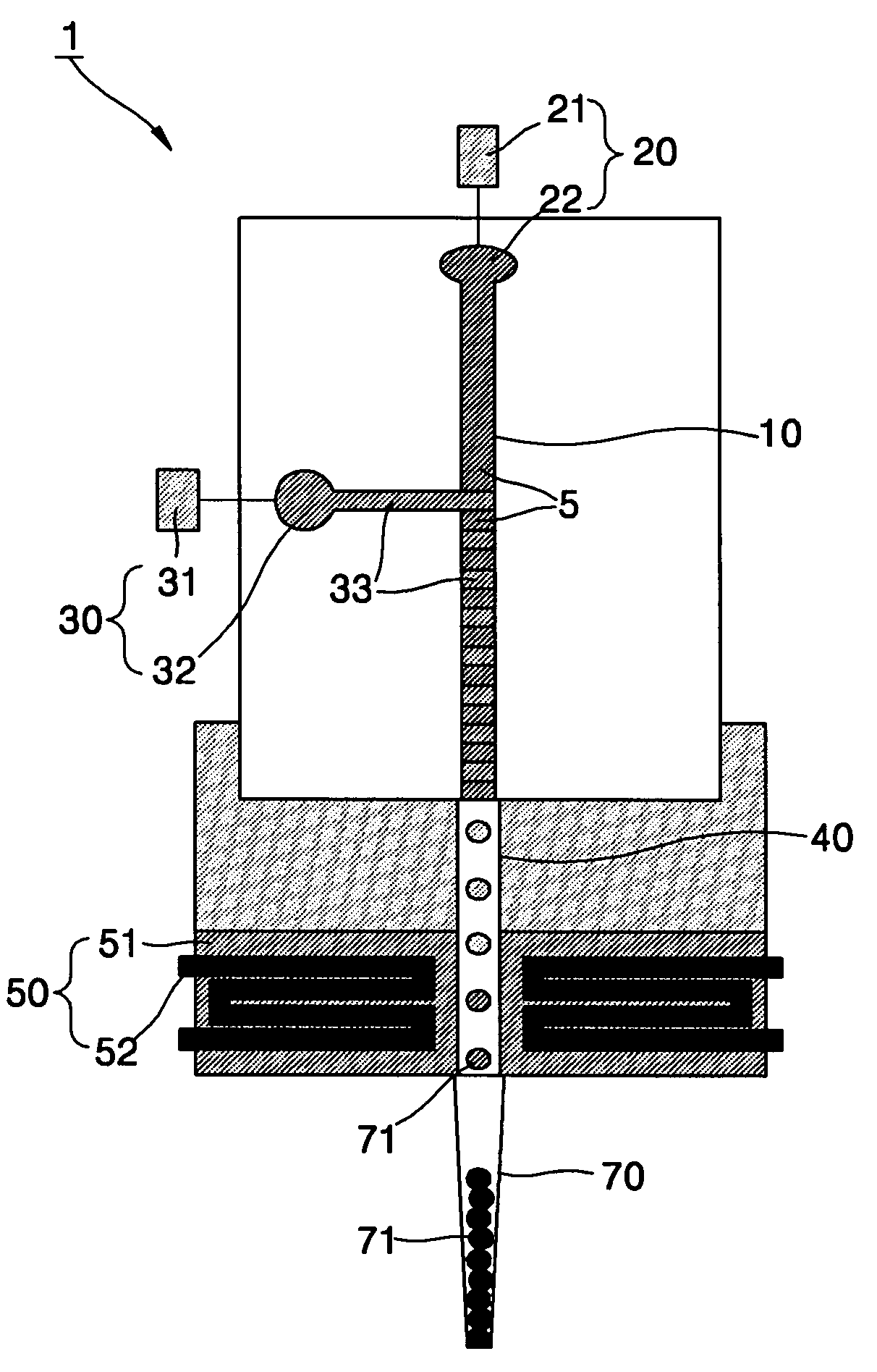
A spotting device for manufacturing a DNA microarray and a spotting method using the same are provided. The spotting device for dropping and immobilizing a solution of biomolecules, for example nucleic acids such as probe DNA, mRNA, and peptide nucleic acid (PNA), and proteins on a DNA microarray surface to manufacture a DNA microarray, includes a first microchannel with a tube shape; a supplying unit supplying the solution of biomolecules to the first microchannel; a biomolecule solution droplet forming unit cross-linked to the first microchannel and forming biomolecule solution droplets with a predetermined size by periodically jetting a gas toward the biomolecule solution flowing in the first microchannel; a second microchannel linked to the first microchannel and having a greater diameter than the first microchannel; a cooling unit surrounding at least a part of the second microchannel to freeze the biomolecule solution droplets which pass through the second microchannel; and a spotting unit thawing the frozen biomolecule solution droplets and dropping the thawed biomolecule solution droplets on a surface of the DNA microarray. The spotting device can form spots with uniform shape, minimize an effect of temperature on biomolecules, and easily manipulate biomolecules when manufacturing a DNA microarray.

Description

BACKGROUND OF THE INVENTION[0001]This application claims the benefit of Korean Patent Application No. 2003-96292, filed on Dec. 24, 2003, in the Korean Intellectual Property Office, the disclosure of which is incorporated herein in its entirety by reference.[0002]1. Field of the Invention[0003]The present invention relates to a spotting device for manufacturing a DNA microarray and a spotting method using the same. More particularly, the present invention relates to a spotting device for dropping and immobilizing a solution of biomolecules, for example, nucleic acids such as probe DNA, mRNA, and peptide nucleic acid (PNA), and proteins on a DNA microarray surface to manufacture a DNA microarray and a spotting method using the same.[0004]2. Description of the Related Art[0005]With progress on the human genome project, a demand for a method to rapidly provide an enormous amount of genetic information with regard to the diagnosis, treatment, and prevention of hereditary diseases has gr...

Claims


Application Information

Patent Timeline
Patent Type & Authority Patents(United States)
IPC IPC(8): B01L3/02G01N1/10B01J19/00C12Q1/68C40B40/06C40B40/10C40B60/14G01N35/00G01N35/10
CPCB01J19/0046B01L3/0244B01L3/0248B01L3/0268B82Y30/00Y10T436/2575B01J2219/00369B01J2219/00529B01J2219/00576B01J2219/00585B01J2219/00596B01J2219/00605B01J2219/00608B01J2219/00659B01J2219/00677B01J2219/00722B01J2219/00725B01J2219/00729B01L2200/0673B01L2300/1827B01L2300/1894B01L2400/02B01L2400/0475B01L2400/0633C40B40/06C40B40/10C40B60/14G01N35/1074G01N2035/00158G01N2035/00237G01N2035/1034B01J2219/00367C12Q1/68
Inventor LEE, JEONG-GUNLEE, HUN-JOO
Owner SAMSUNG ELECTRONICS CO LTD
Learn More