
Display controller, display control method, and image display device

a display controller and control method technology, applied in the direction of instruments, computing, processor architecture/configuration, etc., can solve the problems of increasing the power consumption of the whole display system, difficult to realize the increase in clock frequency, and crucial drawbacks in the mounting area, so as to reduce the load of processing on the external device, increase the mounting area, and increase the power consumption

Inactive Publication Date: 2008-08-26
SHARP KK
View PDF27 Cites 4 Cited by
  • Summary
  • Abstract
  • Description
  • Claims
  • Application Information

AI Technical Summary

Benefits of technology

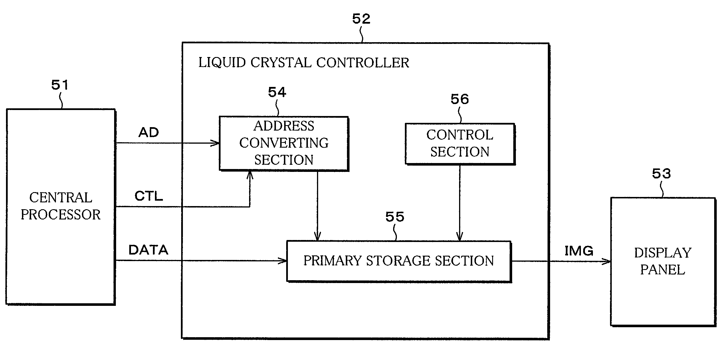
[0019]In the above arrangement, the image data and the address conversion parameter first are inputted from the external device. Here, the external device is, for example, equivalent of a device which creates and edits images to be displayed and processes a variety of information. The address conversion parameter indicates a method of converting the address of each pixel with respect to the image data, so that the display address generating means can generate the display address in accordance with this address conversion parameter. Therefore, unlike the conventional display controller, it is not necessary to obtain address data which indicate address information of each pixel with respect to the image data from the external device. Accordingly, unlike the conventional display controller, an address bus with a width of plural bits for transmitting an address data signal is not required to be provided between the external device and the display controller. This makes it possible to resolve the problems caused in providing the address bus with a width of plural bits, that is, the problem of increase in mounting area due to increase in terminals, the problem of increase in power consumption by parasitic capacitance of the address bus, and the problem of EMI.
[0020]Further, unlike the conventional display controller, it is not necessary to perform address conversion processing in the external device, so that it is possible to reduce the load of processing on the external device. Therefore, even in case where the load on the external device becomes large, for example, by processing the display of a high-resolution motion picture, it is possible to improve the processing ability of the external device by causing the display controller to take the load required for the address conversion processing.
[0024]In the above method, the image data and the address conversion parameter first are inputted from the external device. That is, in the above method, the address data signal which indicates address information of each pixel with respect to the image data is not sent from the external device to the display controller. Accordingly, unlike the conventional method, an address bus with a width of plural bits for transmitting an address data signal is not required to be provided between the external device and the display controller. This makes it possible to resolve the problem of increase in mounting area due to increase in terminals, the problem of increase in power consumption by parasitic capacitance of the address bus, and the problem of EMI.
[0025]Further, the address conversion processing is performed by the display address generating means. Accordingly, unlike the conventional method, it is not necessary to perform the address conversion processing in the external device, so that it is possible to reduce the load of processing on the external device. This makes it possible to improve the processing ability of a system.

Problems solved by technology

However, it is difficult to realize the increase in the clock frequency.
In case where a display system is applied to the apparatuses that reduction in size is required, such as portable apparatuses, increase in a mounting area is a crucial drawback.
Power consumption by parasitic capacitance of signal wiring of which the address bus is composed, which is not negligible, causes increase in power consumption of the whole display system.
Especially, in case of application of the display system to portable apparatuses, power consumption is required to be as low as possible.
Also, as described above, the electric potential in the address bus can be switched at a high speed, so that a problem of EMI (Electro Magnetic Interference) arises.

Method used


Image

  • Display controller, display control method, and image display device
  • Display controller, display control method, and image display device
  • Display controller, display control method, and image display device

Examples


Embodiment Construction

[0040]Referring to FIGS. 1 through 12, an embodiment of the present invention is described as follows.

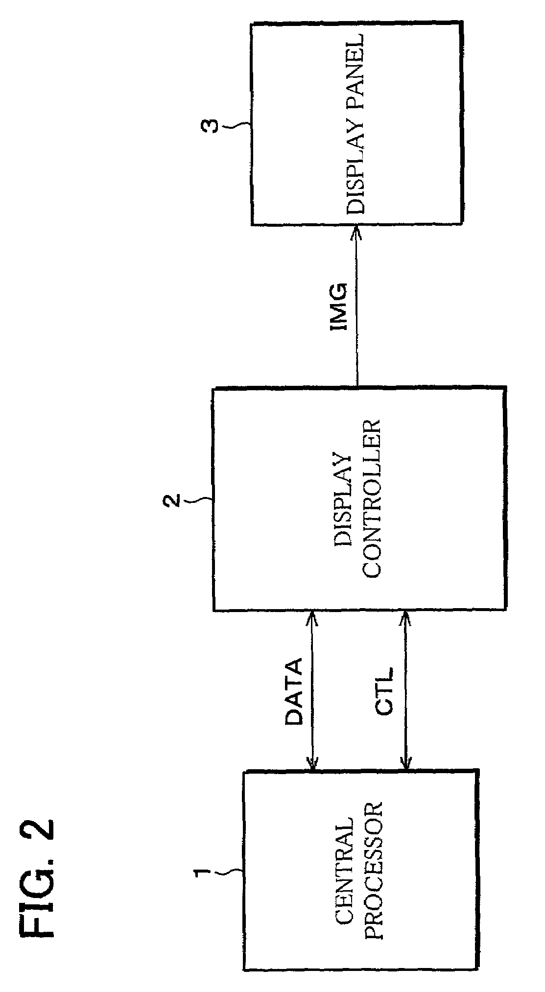
[0041]FIG. 2 is a block diagram schematically showing an arrangement of an image display system according to the present embodiment. As shown in FIG. 2, the image display system includes a central processor 1, a display controller 2, and a display panel 3.

[0042]The central processor 1 is a block which creates and edits images to be displayed and processes a variety of information of the whole image display system. The central processor 1 is composed of, for example, a CPU (Central Processing Unit) as calculating means, a RAM (Random Access Memory) as a working area, and an EEPROM (Electrically Erasable / Programmable Read Only Memory) as a nonvolatile memory. For example, a program, read out on the RAM from the EEPROM, is executed by the central processor 1 to carry out various image processing and information processing. In case where the central processor 1 is connected to communica...


PUM


Abstract

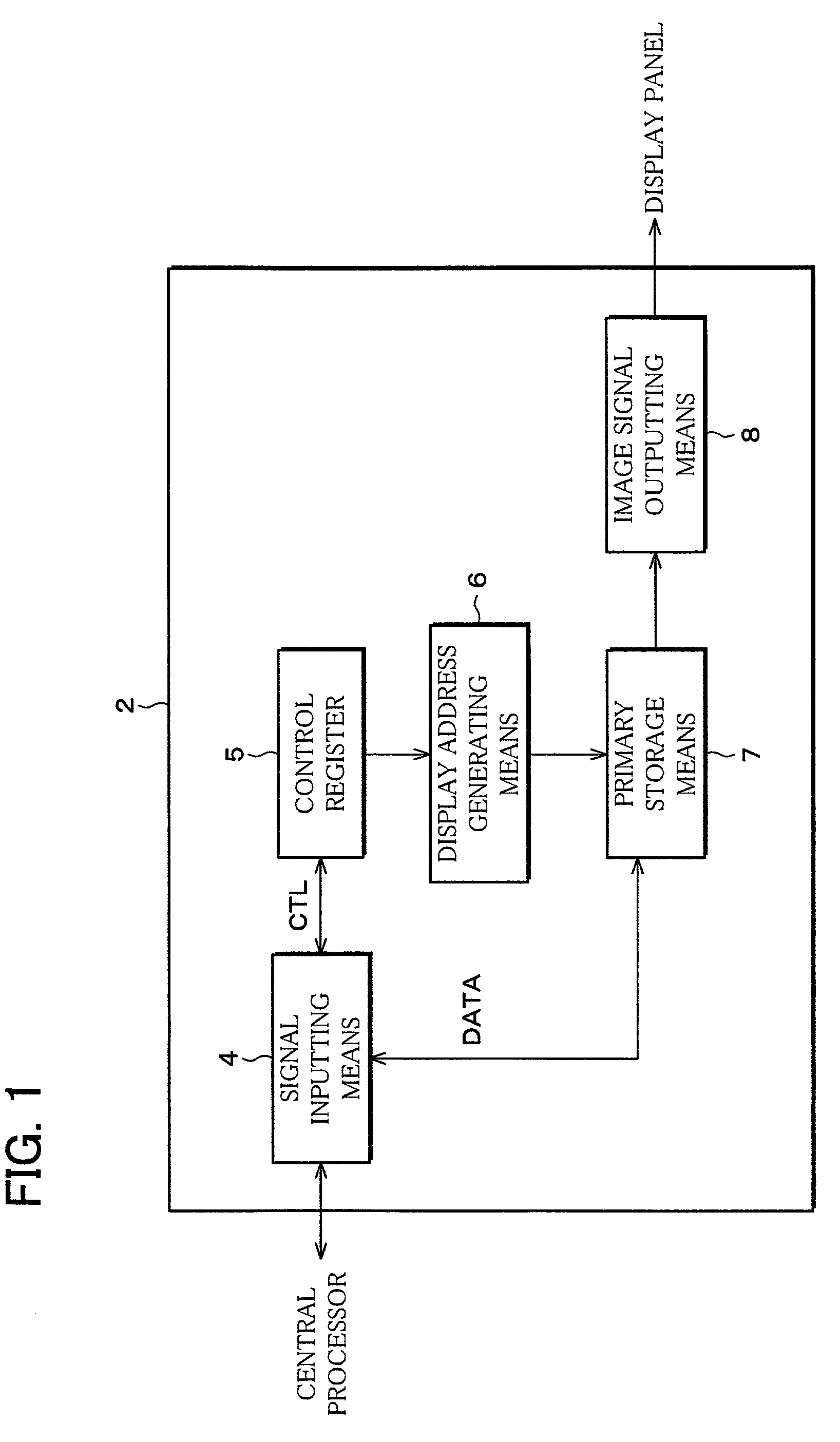
A color data signal (DATA) and the control signal (CTL) are supplied from a central processor to a display controller, and an address conversion parameter included in the control signal (CTL) is stored in a control register 5. In accordance with the address conversion parameter, display address generating means 6 performs address conversion to generate a display address, and in accordance with the display address, the color data signal (DATA) is stored in a primary storage means 7. Thereafter, an image signal is outputted via image signal outputting means 8 to a display panel. This makes it possible to provide the display controller which can reduce a mounting area and power consumption and reduce the load of a processing on the central processor which performs a processing for editing image data.

Description

FIELD OF THE INVENTION[0001]The present invention relates to a drive control operation of display devices such as a liquid crystal display device and an EL (electroluminescent) display device. More specifically, the invention relates to a display controller which performs an address conversion of image data.BACKGROUND OF THE INVENTION[0002]Display devices of various electronic apparatuses, which include devices such as a liquid crystal display device, have been sophisticated from year to year. For example, as display performance of the display device, high gradation display has been required. Moreover, contents displayed on the display device have been required to be not only a still picture but also a motion picture. With such a sophisticated display device, information that is necessary for displaying is increasing.[0003]A system for displaying includes devices such as a central processor, a display control device, and a display device. The central processor processes a variety of...

Claims


Application Information

Patent Timeline
Patent Type & Authority Patents(United States)
IPC IPC(8): G09G5/00G06F12/00G09G3/36G09G3/00G09G5/36G09G5/393
CPCG09G5/393G09G2340/0492G06T1/20G09G3/36G09G3/3208G09G2330/021
Inventor KOJIMA, KIPPEINAKATANI, HIRONORIWATANABE, YASUYUKISAKAMOTO, AKIRA
Owner SHARP KK
Learn More