Data receiving device
a data receiving and data technology, applied in the direction of line-transmission details, synchronisation signal speed/phase control, system details, etc., can solve the problem of long transmission distance and high transmission data rate conflict, limited signal attenuation per transmission unit length, and the tendency of reception faults to occur for specific transition patterns. to achieve the effect of stably compensating a high frequency attenuation, low error rate and low power consumption
- Summary
- Abstract
- Description
- Claims
- Application Information
AI Technical Summary
Benefits of technology
Problems solved by technology
Method used
Image
Examples
example 1
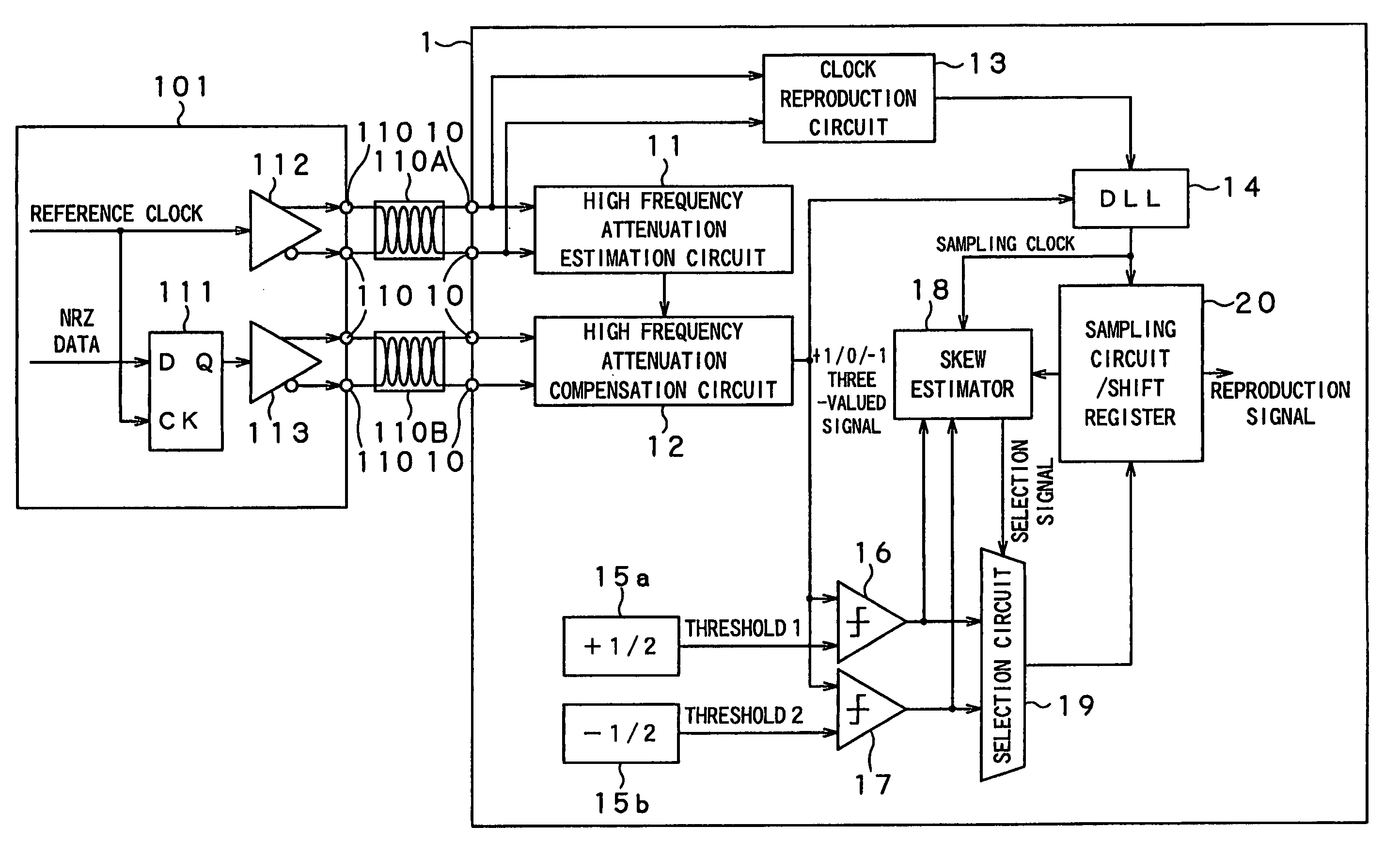
[0044]A concrete example of the present invention will be described in detail with reference to the accompanying drawings. FIG. 3 shows a data receiving device 1 according to the first concrete example of the present invention.
[0045]A data transmitting device 101 that transmits data to a data receiving device 1 outputs NRZ data in synchronization with a reference clock by means of an FF (flip-flop) 111. The amplifiers 112 and 113 amplify the reference clock and NRZ data, respectively, and generate inversion signals. The amplified reference clock and NRZ data are then transmitted to differential conductor pairs (e.g., twisted-pair cable) through a transmitting end 110.
[0046]The data receiving device 1 includes receiving ends 10 to be connected to a differential conductor pair 110A that transmits the reference clock and a differential conductor pair 110B that transmits the NRZ data. The receiving ends of the differential conductor pair 110A are connected to an input of a high frequenc...
example 2
[0081]A second concrete example of the present invention is shown in FIG. 15. A data receiving device 2 of the second concrete example is featured in that a reference clock is not NRZ data itself, but a signal divided the clock signal by a fixed ratio M, and a multiplication by M circuit 81 is provided in place of the clock reproduction circuit 13. Therefore, a data transmitting device 101 includes an M frequency-division circuit 82 and thereby a clock signal of the NRZ data is frequency-divided by M. In FIG. 15, the same parts as those in FIG. 3 are indicated by the same reference numerals, and the description thereof will be omitted.
[0082]FIG. 16 shows a configuration of a high frequency attenuation characteristics estimation circuit 83 suitably used in the second example. This circuit includes an S / H 84 and S / H 85 that sample the reference clock, in which high frequency attenuation has been compensated, output from the adder 25. The high frequency attenuation characteristics esti...
PUM
 Abstract
Description
Claims
Application Information
 - R&D
- Intellectual Property
- Life Sciences
- Materials
- Tech Scout
- Unparalleled Data Quality
- Higher Quality Content
- 60% Fewer Hallucinations
Browse by: Latest US Patents, China's latest patents, Technical Efficacy Thesaurus, Application Domain, Technology Topic, Popular Technical Reports.
© 2025 PatSnap. All rights reserved.Legal|Privacy policy|Modern Slavery Act Transparency Statement|Sitemap|About US| Contact US: help@patsnap.com


