Multi-core fiber

a fiber and multi-core technology, applied in the field of multi-core optical fibers, can solve the problems of fluorescence diagnostics carried out in combination with an endoscope that attract a great deal of attention

Active Publication Date: 2008-08-26
THE FUJIKURA CABLE WORKS LTD
View PDF16 Cites 222 Cited by
  • Summary
  • Abstract
  • Description
  • Claims
  • Application Information

AI Technical Summary

Benefits of technology

[0008]Certain embodiments of the present invention provide a multi-core optical fiber contributive to accurate fluorescence diagnostics.

Problems solved by technology

Further, fluorescence diagnostics carried out in combination with an endoscope attracts great deal of attention.

Method used


Image

  • Multi-core fiber
  • Multi-core fiber
  • Multi-core fiber

Examples


Embodiment Construction

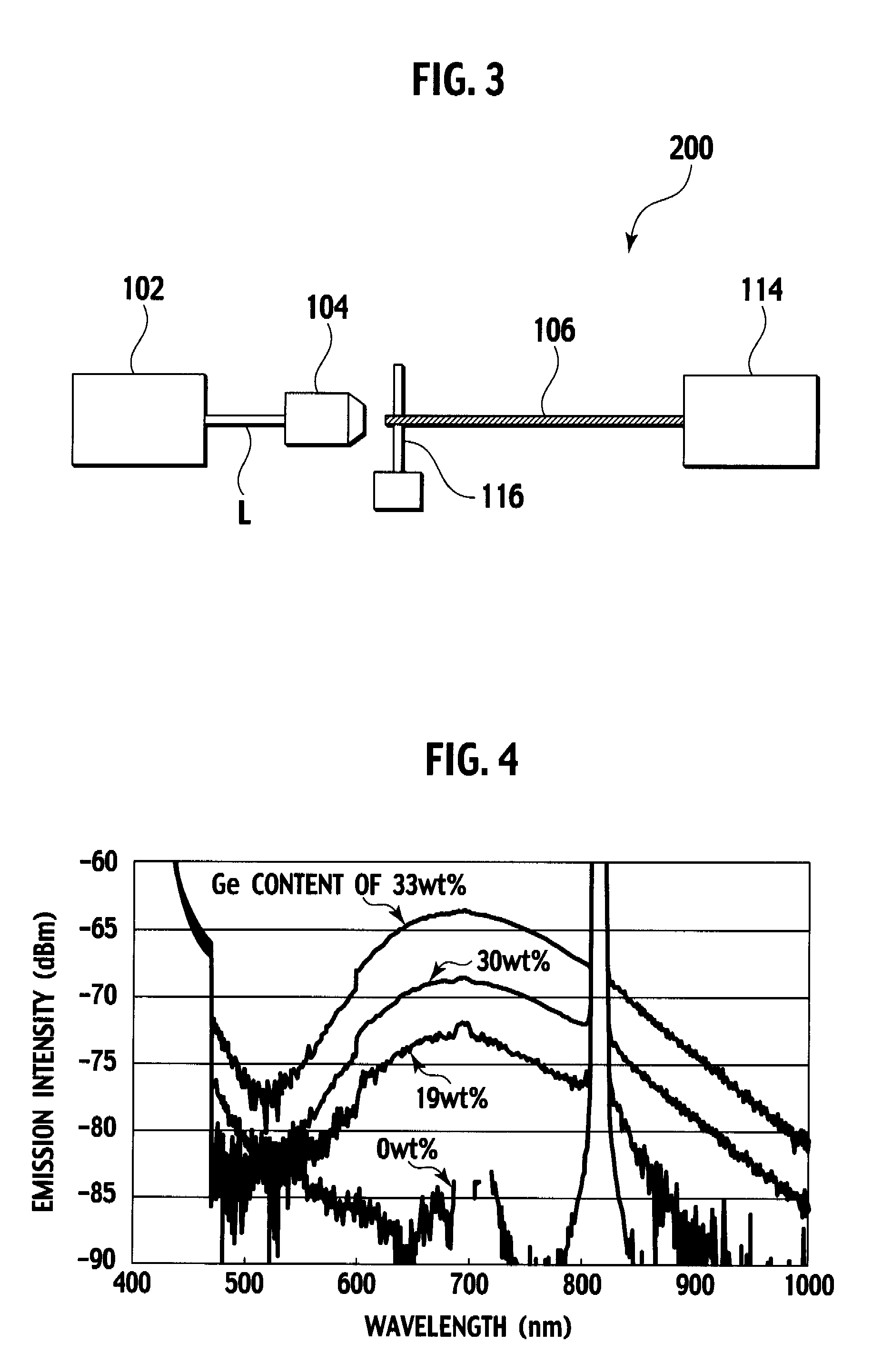
[0018]FIG. 6 schematically illustrates a measuring device 100 pertaining to a study about a spectra of lights collected by a multi-core optical fiber.

[0019]The measuring device 100 is comprised of a light source 102 from which laser light of 488 nm in wavelength is emitted as excitation light, an optical lens 104 for condensing the laser light into a beam of from 2 to 3 μm in diameter, a multi-core optical fiber 106 so positioned as to receive the beam, an objective lens 108 provided at an output end of the multi-core optical fiber 106, and a CCD 110 optically coupled to the objective lens 108. The measuring device 100 further includes a dichroic filter 112 allowing laser light from the light source 102 to pass through and reflecting light reflected by the objective lens 108 and passing through the multi-core optical fiber 106 and the optical lens 104 in this order, and a spectrum analyzer 114 to receive the light reflected by the dichroic filter 112 (light reflected by the objectiv...


PUM

PropertyMeasurementUnit
diameteraaaaaaaaaa
refractive index profile factoraaaaaaaaaa

Abstract

A multi-core optical fiber apparatus is disclosed. The multi-core optical fiber apparatus includes a cladding comprising quartz and a plurality of cores embedded in the cladding. Each of the cores has a diameter (D) ranging from 1.3 μm to 2.0 μm, a numerical aperture (NA) from 0.35 to 0.45 and a refractive index profile factor (α) from 2.0 to 4.0. A center of each of the cores has a germanium content of 20 wt % to 30 wt %. An interval between adjacent cores is 3.0 μm or more.

Description

CROSS-REFERENCE TO RELATED APPLICATIONS[0001]This application claims priority from Japanese Patent Application No. 2006-300505 filed on Nov. 6, 2006; the entire contents of which are incorporated herein by reference.BACKGROUND OF THE INVENTION[0002]1. Field of the Invention[0003]Apparatuses consistent with the present invention relates to a multi-core optical fiber preferably applied to an imaging method using an optical fiber such as a confocal fluorescent imaging method.[0004]2. Description of the Related Art[0005]In many medical fields such as gastroenterology, pulmonary disease, or cardiovascular disease, endoscopes are employed for direct observation of surfaces of tissues or as auxiliary apparatuses for medicine. Further, fluorescence diagnostics carried out in combination with an endoscope attracts great deal of attention.[0006]A tissue irradiated and excited by excitation light emits a fluorescent light having a characteristic spectrum. When the tissue has a lesion such as a...

Claims


Application Information

Patent Timeline
Patent Type & Authority Patents(United States)
IPC IPC(8): G02B6/02
CPCG02B6/02042
Inventor KUDOU, MANABUAIKAWA, KAZUHIKOTSUMANUMA, TAKASHI
Owner THE FUJIKURA CABLE WORKS LTD
Why Eureka
Try Eureka