
Device for thermal ablation of a cavity

Inactive Publication Date: 2008-09-02
IDOMAN RMD LTD
View PDF42 Cites 60 Cited by
  • Summary
  • Abstract
  • Description
  • Claims
  • Application Information

AI Technical Summary

Benefits of technology

[0002]Medical treatments involving ablation of the endometrium of the uterus are well known in the prior art. The endometrium is the portion of the uterine lining to which an embryo normally attaches and is responsible for the menstrual cycles. Such ablation treatments typically involve either the direct or indirect application of heat or cold to the endometrial tissue. Commonly, ablation devices and techniques have been used to treat menorrhagia (a condition of excessive menstrual bleeding) by cauterizing, or inducing necrosis of the endometrial lining. This cauterization prevents further proliferation of the endometrium and may result in permanent relief of menorrhagia symptoms.

Problems solved by technology

Such alternative ablation techniques also pose higher risk of perforating the uterus, normally require use of general anesthesia, and have a higher incidence of post-operative complications than thermal balloon ablation techniques.
In spite of the potential advantages of thermal balloon ablation techniques over alternative treatment methodologies, problems with the thermal balloon ablation apparatuses in the prior art have prevented such devices from being adopted widely for use in the treatment of menorrhagia.
During heating, these devices often develop temperature gradients in the liquid which can result in uneven treatment of the endometrial surface.
Placement of the heating element relative to the balloon walls is difficult to control in practice.
However, such circulating methodologies add cost and complexity to the apparatus and the ability to achieve desired temperature uniformity depends among other factors on the volume of liquid within the balloon.
This has limited the variety of liquids to those typically found in a clinical environment (e.g. D5% W or saline).
Heating liquid to the boiling point can result in a dangerous increase in balloon volume due to expansion of gas and in uneven treatment since the presence of this gas pockets in the balloon act to thermally insulate the adjacent tissue.
The maximum temperature limitation of these liquids has resulted in relatively long treatment times; it is well established in the research and in clinical practice that it requires in approximately 8 minutes to cauterize the endometrium by thermal balloon ablation using liquid temperatures of 85 C. Furthermore, the use of liquid temperatures in the range of 70-90 C makes the use of liquid heating means external to the uterus or balloon ineffective since in this temperature range there is insufficient heat energy contained within the volume of liquid within the uterus to adequately cauterize the endometrium.
In addition, devices with heating elements located in the balloon within the uterus prohibit the use high viscosity liquids (such as 100% Glycerin) which resist flow at ambient temperatures but once heated become less viscous and can readily flow through a catheter to inflate a balloon placed in the uterus.
Systems which require the operator to supply the inflation liquid are also complicated for the operator to use.
This process also compromises the sterility of the system since there is potential for non-sterile or contaminated liquid to circulate within the balloon.
In the event of a balloon leak or rupture, this non-sterile liquid is released into the uterine cavity and could result in infection.
Devices in the prior art typically rely on mechanical actuators, syringes, or liquid pumps which come into contact with the treatment liquid in order to control inflation and pressurization of the balloon, these can be expensive, unreliable, and subject to contamination.
Furthermore such systems (such as that disclosed by Stevens et a—U.S. Pat. No. 5,800,493) typically have expensive disposable components as these components often include hoses, valves, connectors, electrical wiring, syringes, and heating elements which must be disposed of after each use.
Often it is difficult for the operator to control inflation pressure and there is not adequate means to control this pressure in response to changes in uterine volume during treatment (typically the uterus relaxes and expands as treatment progresses and therefore it is desirable to increase the volume of liquid in the balloon to maintain a constant inflation pressure).
Wallsten et al U.S. Pat. No. 5,693,080 discloses apparatus intended to allow automated control of inflation pressure through mechanical actuation of syringes or similar means however this is costly and does not allow fine control of pressures.
Wallsten et al further disclose a means for providing overpressure relief in the event of a increase in balloon pressure such as that which might be caused by a sudden contraction of the uterus during treatment however this does not provide a practical or inexpensive means for automated control of balloon inflation, deflation, and liquid pressure.
There is a danger of perforating the uterus by over-inserting the catheter if the clinician does not perform this operation properly.
Because of the high viscosity at ambient temperatures, such liquids could not be readily utilized in apparatus where the heating means is located inside the balloon which is inserted into the uterus.

Method used


Image

  • Device for thermal ablation of a cavity
  • Device for thermal ablation of a cavity
  • Device for thermal ablation of a cavity

Examples


Embodiment Construction

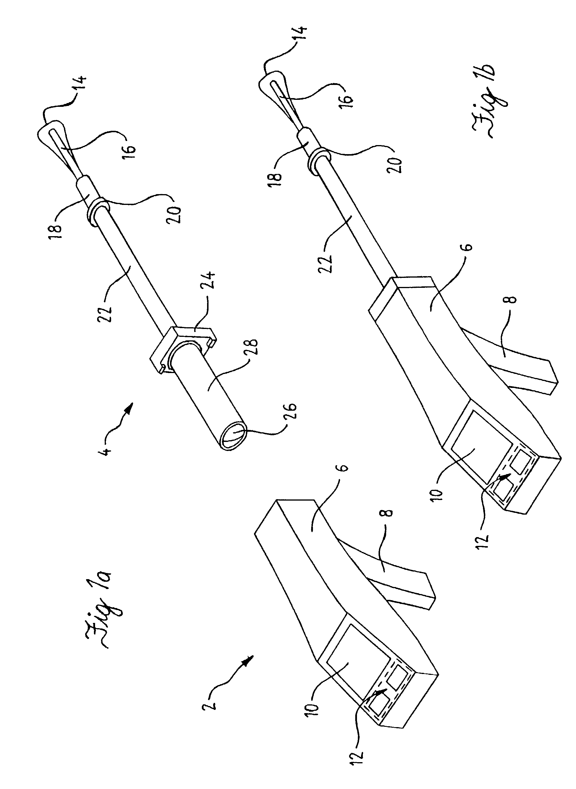
[0035]As shown in the drawings for the purposes of illustration, the present invention is embodied in a thermal balloon ablation apparatus which comprises a reusable component and a disposable component for delivering therapy to a body cavity.

[0036]In accordance with the present invention as shown in FIG. 1a and FIG. 1b, the thermal balloon ablation apparatus comprises a reusable component 2 and a disposable component 4. Reusable component 2 further comprises a housing 6 which has a handle 8. Integral to housing 6 is a display means 10 and user controls 12. Disposable component 4 comprises a distal balloon 14, a semi-rigid or rigid catheter 16 having a distal and proximal end, a semi-rigid or rigid distal sheath 18, a flange 20, a semi-rigid or rigid proximal sheath 22, a pneumatic fitting 24, a proximal balloon 26, and a protective shield 28.

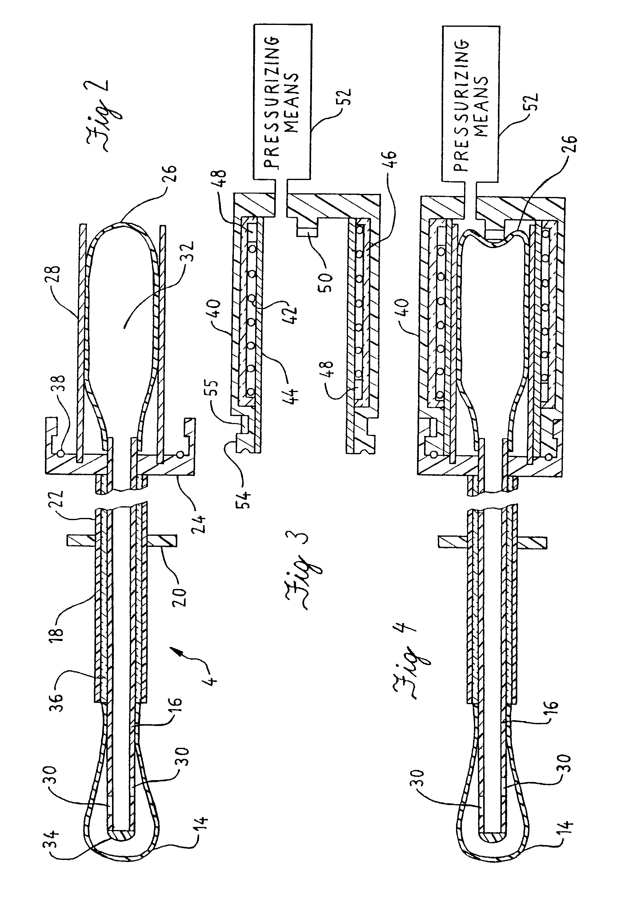
[0037]FIG. 2 shows a detailed cross sectional view of disposable component 4. Distal balloon 14 can be inflated to volumes of 30 ml without ge...


PUM


Abstract

An apparatus and method for causing necrosis of tissue and specifically intended for thermal ablation of the uterine cavity to cauterizing the endometrial tissue. The apparatus includes a liquid-tight, liquid filled system having a distal flexible member; a proximal flexible member; and a catheter joining and providing a liquid path between these distal and proximal members. The apparatus further includes a pressurizable pneumatic chamber into which the proximal flexible member is inserted and a means to controllably heat the contents of the pneumatic chamber. The system operates to: first withdraw substantially all of the liquid into the proximal flexible member contained within the pressurizable pneumatic chamber; second to heat this liquid to a temperature such that it can cause tissue necrosis; and third to force the heated liquid from the proximal flexible member into the distal flexible member where it is maintained for a predetermined time and at a predetermined pressure. Where this distal member has been inserted into a uterine cavity or is otherwise is in contact with living tissue, the presence of the heated liquid results in tissue necrosis and cauterization.

Description

TECHNICAL FIELD[0001]The disclosed invention relates to an apparatus or device for effecting hyperthermia in a body cavity or duct. More specifically, the invention relates to apparatus and methods using a balloon or similar flexible bladder which is inserted into the uterus and filled with a heated liquid at a known pressure and for a known time in order to cauterize (“ablate”) the endometrium of the uterus. This method of treatment is known as “thermal balloon ablation”.BACKGROUND AND SUMMARY OF THE INVENTION[0002]Medical treatments involving ablation of the endometrium of the uterus are well known in the prior art. The endometrium is the portion of the uterine lining to which an embryo normally attaches and is responsible for the menstrual cycles. Such ablation treatments typically involve either the direct or indirect application of heat or cold to the endometrial tissue. Commonly, ablation devices and techniques have been used to treat menorrhagia (a condition of excessive mens...

Claims


Application Information

Patent Timeline
IPC IPC(8): A61F7/12A61B17/42A61B17/00A61B18/04A61B18/08
CPCA61B18/08A61B2017/00092A61B2018/046A61B2017/4216A61B2017/00544
Inventor MARKO, ALEXEIMCDOUGALL, IANYACKEL, DOUGLASSBRUCE, MONTY
Owner IDOMAN RMD LTD
Learn More