Surgical implement detector

a detector and surgical technology, applied in the field of radiofrequency identification (rfid) markers for the detection of surgical implements, can solve the problems of gyro-magnetic effect producing a relatively weak signal, most of the higher order microwave frequency signals are lost before any non-linear transponder can be detected, and the effect of high reliability in operation

Active Publication Date: 2008-09-02
INNOVO SURGICAL INC +1
View PDF14 Cites 117 Cited by
  • Summary
  • Abstract
  • Description
  • Claims
  • Application Information

AI Technical Summary

Benefits of technology

[0039]The present invention is a surgical implement detector consisting of radiofrequency identification (RFID) marker and a detection unit. This RFID tag or marker may be a passively-powered device with a read-only memory of burned-in digital code or a user programmable memory. It may not necessarily rely on battery power although active powering of the RFID tags may be a suitable option depending on desired performance parameters. The surgical implement detector is highly reliable in operation and capable of detecting various surgical implements such as metallic and non-metallic instruments including surgical sponges, gauze pads, and other items to which the radiofrequency marker is attached. The RFID marker can be very small in size and is typically encapsulated in glass or inert polymer making it able to withstand cleaning and sterilization operations. It is not adversely affected by blood or saline solution present in a surgical wound.

Problems solved by technology

Unfortunately, substantially all of the higher order microwave frequencies generated by the transponder are readily absorbed by the human body.
Consequently, most of the higher order microwave frequency signals are lost before any non-linear transponder can be detected.
In addition, the gyro-magnetic effect produces a relatively weak signal.
Inasmuch as there is no means to verify the status of the battery, this method for detection of surgical implements is vulnerable to battery failure.
Such a response does not comprise a digital code as it lacks the capacity for identifying a surgical implement.
Information is not digitally encoded and therefore the marker has no means for identifying individual counting objects.
This system does not locate sponges or surgical pads misplaced in a surgical cavity.
Further, there is no indication in the Levin application that the RFID devices are scanned during surgery to establish the location of the sponge or surgical pad.
The Uozumi et al. system does not detect sponges and surgical pads in a surgical wound, since they are not expected to overlap.
The markers resonate at preselected frequencies in the form of sinusoidal waves, but do not provide digital data suited for identifying a sponge or surgical pad.
However, because the sponges are not x-rayed when first put into use and because it is not possible to x-ray the sponges when they are in the patient wound, the Ballard system is incapable of determining whether all sponges have been removed from the patient wound or whether any sponges have been left behind in the patient wound.
The system does not provide digital means for identifying a sponge or surgical pad.
The tag signal has a predetermined frequency in the form of a sinusoidal wave, and does not carry digital information suitable for identifying laparotomy pads or sponges retained within the wound cavity.
It is not a passive device that can be incorporated in a sponge or surgical pad due to the requirement for a reliable power source.
The frequency of information transfer to the reader is very slow, due to the switching on and off action.
Unfortunately, RFID systems such as those used in cattle tracking suffer from several critical deficiencies that detract from their overall utility.
For example, RFID systems designed for cattle identification are understood to be limited to a range of just a few inches.
Unfortunately, in surgical applications, a greater range is required.
Another deficiency of prior art RFID systems is that they are optimized to identify one or more RFID tags which are harmless to the environment being interrogated such as in a cattle yard, on a warehouse pallet, or in toll booth lane.
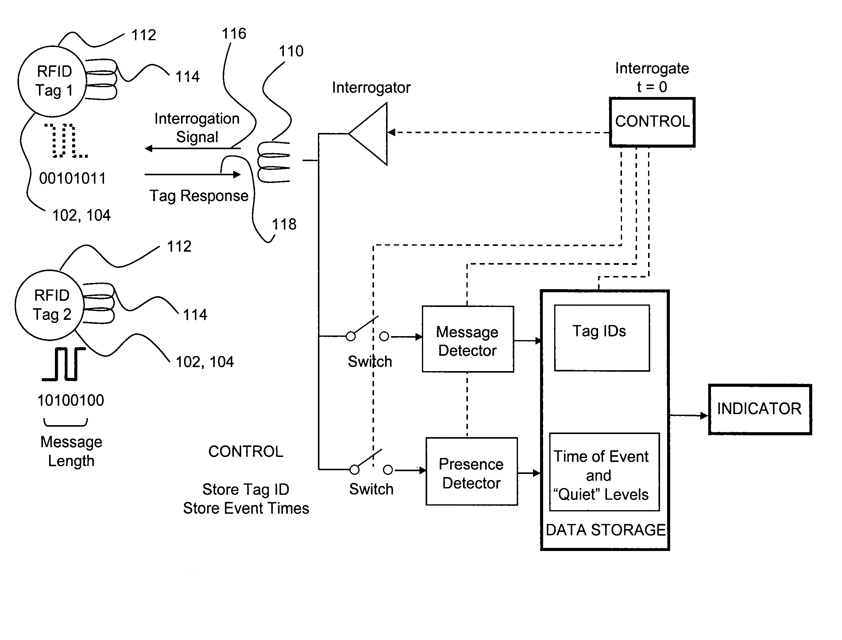
Unfortunately, the presence of two or more RFID tags within range of the detector generally results in a failure to acquire identification codes from any of the RFID tags due to “data collision” between the RFID tags.
In this regard, current RFID readers are generally incapable of determining the presence of multiple RFID tags within a scanned area or of determining the identification code of any one of the RFID tags in an area containing multiple RFID tags.
The above-mentioned deficiencies of current RFID readers could unfortunately mean that either two or more RFID tags are present in the area, or, that there are no RFID tags present in the area being scanned.
As such, there is currently no reliable method using conventional RFID tagging technology to verify whether or not surgical items are present after the end of an operation (i.e., prior to wound close) absent the incorporation of more expensive collision-control RFID tag technology.
Unfortunately, inadvertent retention of surgical items in the patient can result in serious complications for the patient and even death.
Another deficiency of prior art RFID systems is that the range of RFID tag detection is dependent upon the degree to which the RFID reader and the RFID tag are aligned with one another.
Unfortunately, there is no way to determine the orientation of the RFID tag which may be hidden from view in the patient wound.
Therefore, detecting a tagged surgical item may be unsuccessful if the RFID reader antenna is not optimally-oriented with respect to the unseen RFID tag.
As so noted, the ability to detect an RFID tag may be compromised due to misalignment between the RFID tag antenna and the remote detector unit antenna.
Unfortunately, the installation of multiple RFID tags on the same surgical implement will result in data collision between the RFID tags and therefore requires that anti-collision measures be taken.
Unfortunately, this delay in RFID tag response increases the power requirements for each RFID tag.
In a passive system, a limited amount of power is typically collected from the signal transmitted by the RFID reader (i.e., interrogator) such that a battery may be additionally required to provide power for the extended duration due to signal delay.
In addition to the added power requirements, a further deficiency associated with anti-collision technology is that such systems are typically more costly than RFID tag systems that operate on a one-at-a-time basis because they require the tags to have read / write capability.
The increased cost of anti-collision technology in the RFID detection system may be prohibitive when the instrument or implement to which an RFID tag is attached is less expensive than the RFID tag itself.
In addition to these disadvantages encountered in the upper frequency range, further drawbacks are encountered as the Gigahertz range is approached.
As is well known in the art, microwave ovens typically operate at this frequency to heat watery foods and can therefore potentially cause unwanted localized heating (i.e., cooking) of body tissue by inducing rapid vibration of water molecules contained therewithin.

Method used


Image

  • Surgical implement detector
  • Surgical implement detector
  • Surgical implement detector

Examples


Embodiment Construction

[0093]This invention relates to a surgical implement detector or detector system utilizing a radiofrequency identification (RFID) tag or marker which is secured to a surgical implement, whether a surgical sponge, gauze pad, metallic instrument or other item, and is detected by an antenna attached to either a remote, fixed scanner or by a hand-held scanner. Each RFID-tagged item is read by the RFID reading device upon introduction into the operative field, before insertion into the wound and again upon conclusion of surgery, and a record is made thereof. If the upper frequency tag is used, the scanner can also be used to locate the RFID-tagged items within the patient at any time during surgery.

[0094]If the low frequency RFID tag is used, the reader individually identifies each RFID tag upon introduction into the operative field and records it on a list and again identifies and records each tagged item upon removal from the operative field and both inventory lists are matched. When t...


PUM


Abstract

Provided is a detector system for detecting a plurality of items each having at least one RFID tag attached thereto. The detector system may include a presence detector and / or a message detector. The presence detector may include a signal reader which receives modulated carrier frequencies from the RFID tags during a predetermined response time period for comparison to a reference level. The signal reader may be configured as a power integrator or a constellation discriminator. The power integrator sums the power contained in signals transmitted by the RFID tags by integration for comparison to an environmental noise level measurement taken during a quiet period. For the constellation discriminator, bits contained in the modulating message are compared to the bit pattern of a predetermined reference constellation. The detector system may be configured as a 3-state detector which combines the presence detector with a message detector that indicates the identification code of the RFID tags.

Description

CROSS-REFERENCE TO RELATED APPLICATIONS[0001]The present application is a continuation-in-part application of U.S. application Ser. No. 11 / 055,348 entitled SURGICAL IMPLEMENT DETECTOR UTILIZING A RADIO FREQUENCY IDENTIFICATION MARKER filed on Feb. 10, 2005, which is related to U.S. application Ser. No. 11 / 054,844 entitled MULTIMODAL DETECTION OF SURGICAL SPONGES AND IMPLEMENTS filed on Feb. 10, 2005, the entire contents of all being expressly incorporated by reference herein.STATEMENT RE: FEDERALLY SPONSORED RESEARCH / DEVELOPMENT[0002](Not Applicable)BACKGROUND[0003]The present invention relates to radiofrequency identification (RFID) markers for detection of surgical implements and, more particularly, to an RFID marker embedded in or otherwise securely attached to a surgical implement such as a laparotomy pad or sponge, metallic surgical instrument or other implement and which is specifically adapted for preventing the inadvertent retention of such implement(s) during a surgical pro...

Claims


Application Information

Patent Timeline
Patent Type & Authority Patents(United States)
IPC IPC(8): G08B13/14
CPCA61B5/06A61B5/7242G01V15/00A61B2019/448A61B5/6861A61B90/98
Inventor FABIAN, CARL E.O'NEILL, FRANK
Owner INNOVO SURGICAL INC
Why Eureka
Try Eureka