Radiation imaging apparatus, radiation imaging system, and method of controlling radiation imaging apparatus
a radiation imaging and radiation imaging technology, applied in the field of radiation imaging apparatuses and radiation imaging systems, can solve the problems of increasing noise, increasing power consumption and heat generation in the reading circuit, and increasing noise, so as to reduce power consumption, reduce noise, and reduce power consumption
- Summary
- Abstract
- Description
- Claims
- Application Information
AI Technical Summary
Benefits of technology
Problems solved by technology
Method used
Image
Examples
first embodiment
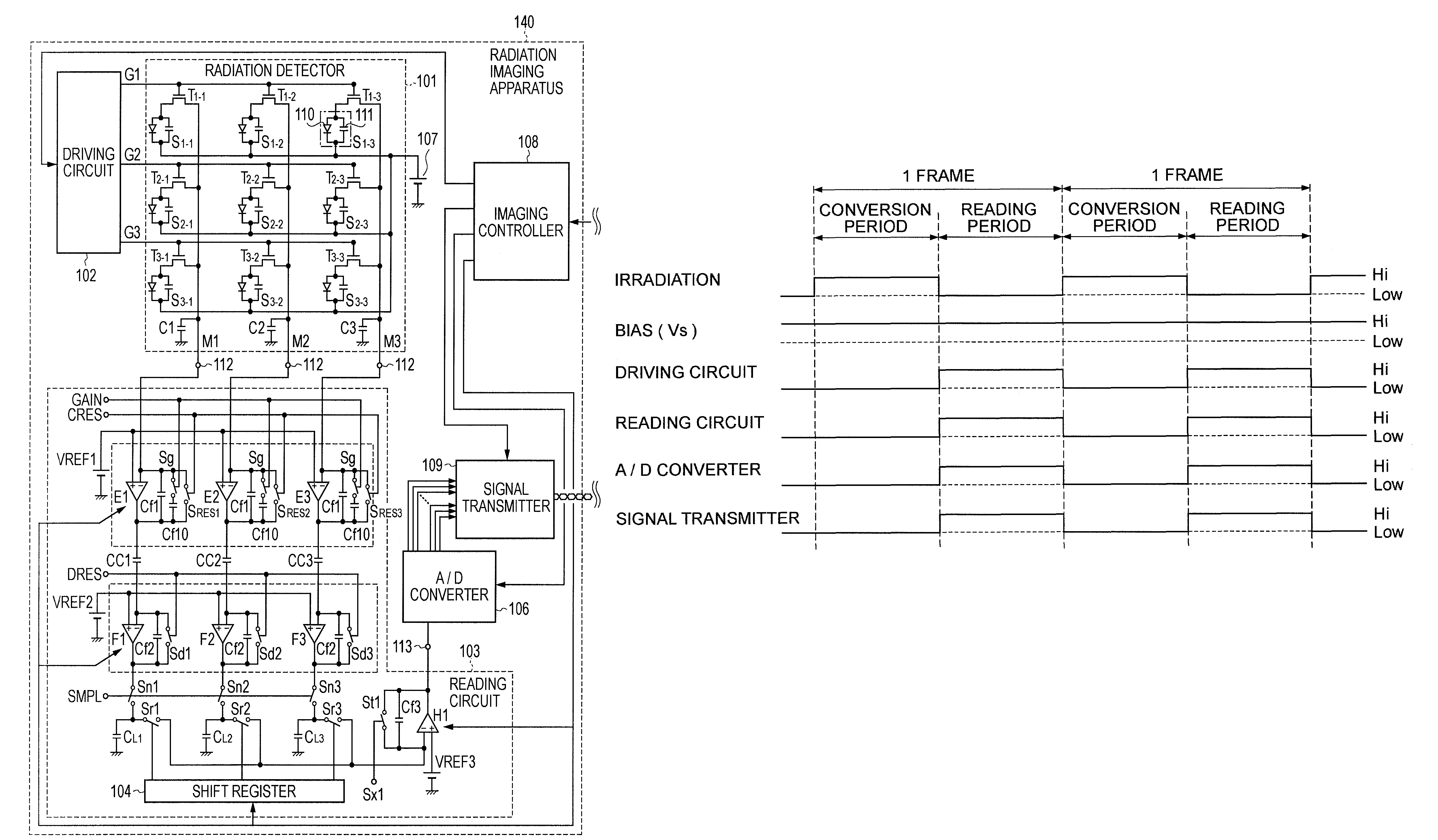
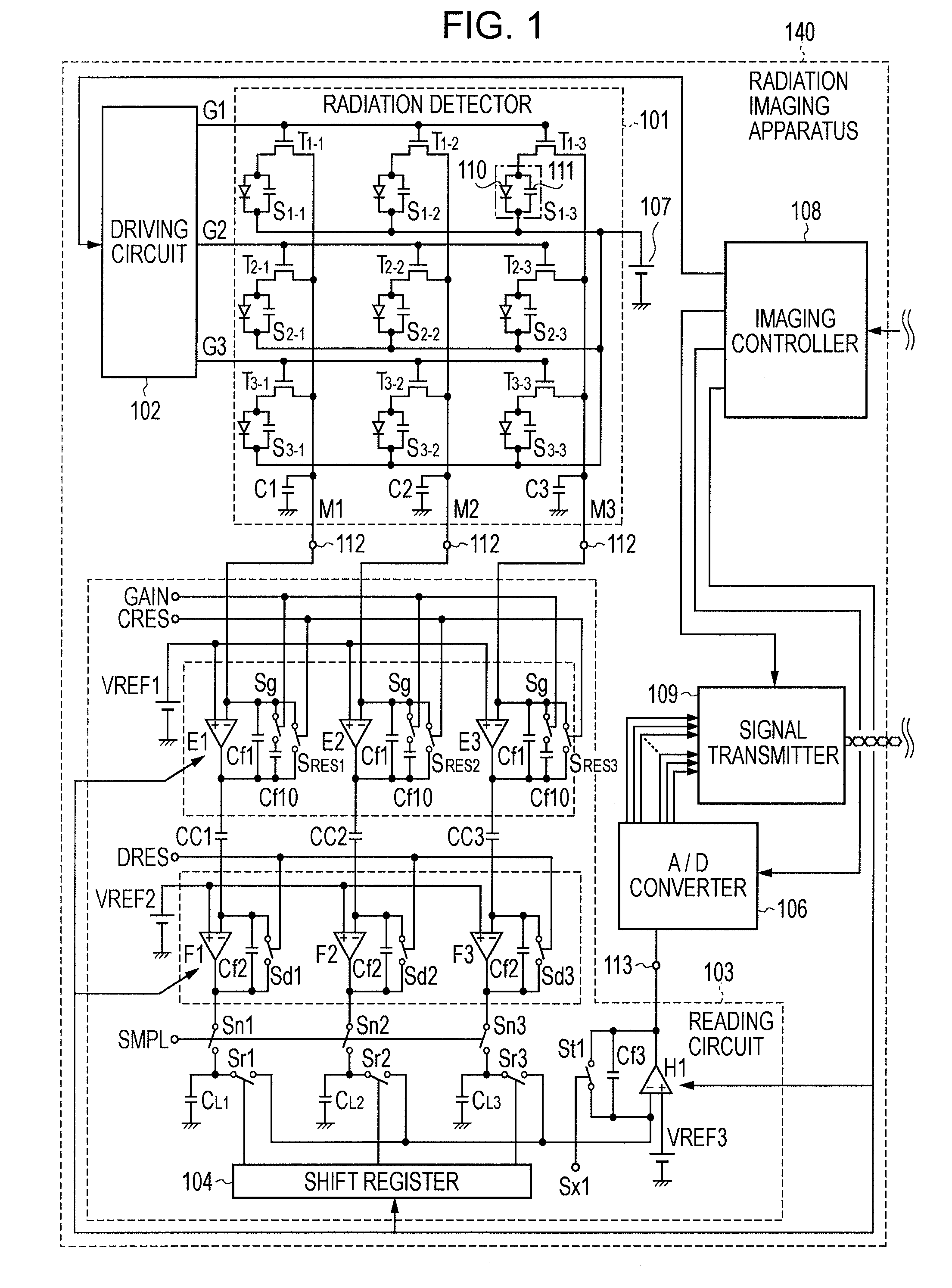
[0029]FIG. 1 is a schematic diagram showing an equivalent circuit of a radiation imaging apparatus according to a first embodiment of the present invention. The radiation imaging apparatus is capable of operating in a moving-picture taking mode for fluoroscopy or the like and a still-picture taking mode for ordinary imaging as selected. In FIG. 1, phosphor members, which function as a wavelength converter that converts radiation rays into visible light, is not shown.
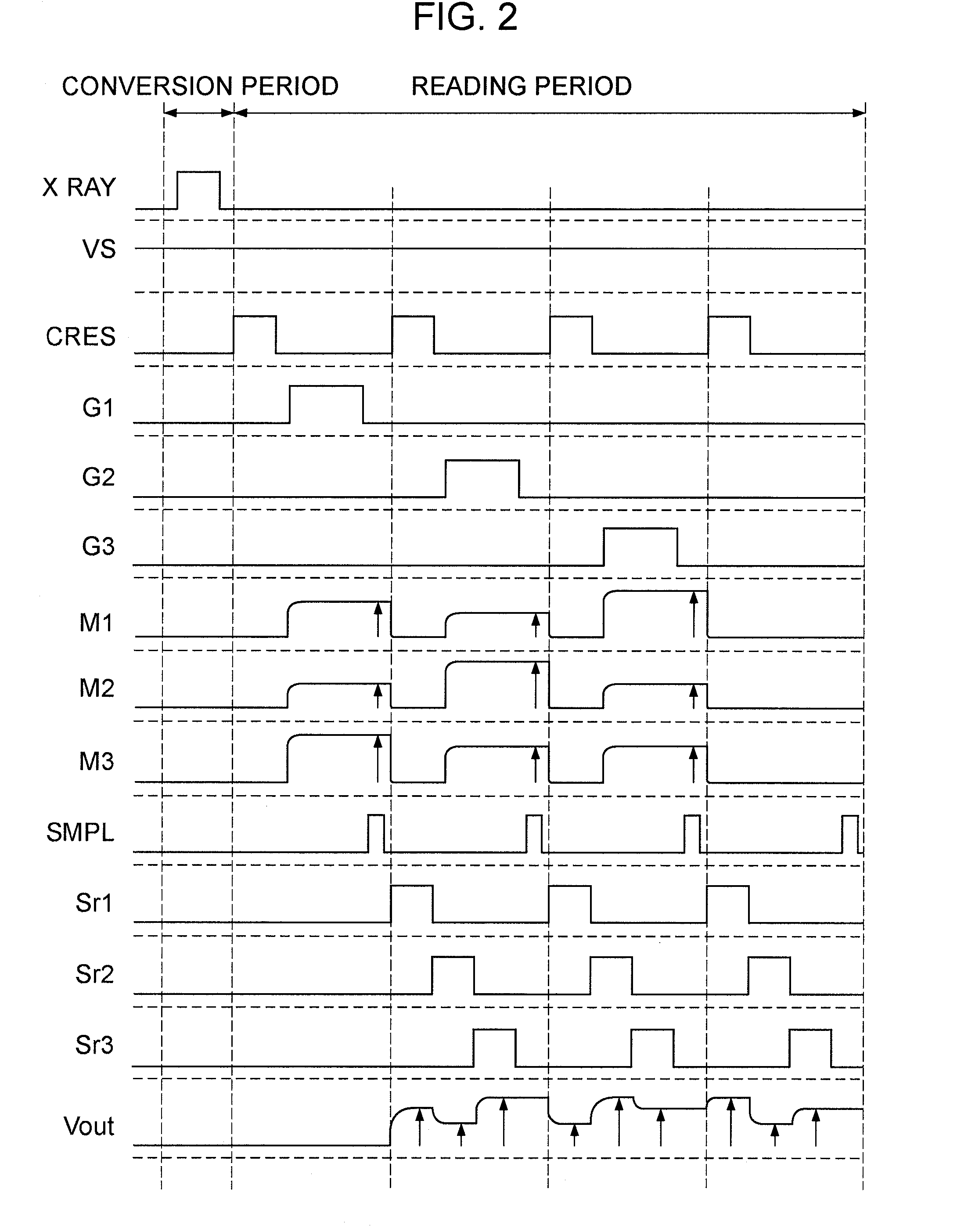
[0030]Referring to FIG. 1, a radiation detector 101 detects radiation rays. In each of a plurality of photoreceptor regions 110, light obtained by wavelength conversion of radiation rays is converted into corresponding charges. The charges obtained by photoelectric conversion in the photoreceptor regions 110 are accumulated in inter-electrode capacitors 111. The radiation detector 101 includes photoelectric converter elements S1-1 to S3-3 each including one of the photoreceptor regions 110 and one of the inter-electrode ...
second embodiment
[0054]Next, a second embodiment of the present invention will be described with reference to FIG. 8. FIG. 8 is a timing chart schematically showing states of operation in this embodiment. Since the configurations of the radiation imaging apparatus and the radiation imaging system are the same as in the first embodiment, description thereof will be omitted.
[0055]In the first embodiment, each frame includes a conversion period (irradiation period) and a reading period. In contrast, in the second embodiment, each frame includes four periods, namely, an offset accumulating period and an offset reading period in addition to the conversion period (irradiation period) and the reading period. The offset accumulating period is a waiting period having the same length as the conversion period (irradiation period), without irradiation with radiation rays. In the radiation imaging apparatus, an offset attributable to a dark component of the converter or an offset component of the reading circuit...
third embodiment
[0056]Next, a third embodiment of the present invention will be described with reference to FIGS. 9 and 10. Components corresponding to those described above are designated by the same numerals, and description thereof will be omitted.
[0057]FIG. 9 is a schematic circuit diagram of one pixel in the radiation imaging apparatus according to this embodiment. FIG. 10 is a timing chart schematically showing an operation of one pixel in the radiation imaging apparatus according to this embodiment.
[0058]This embodiment differs from the first embodiment in that a memory 211 and an image processor 210 are provided between the A / D converter 106 and the signal transmitter 109 in the radiation imaging apparatus. An image A composed of radiation image signals acquired with irradiation is temporarily stored in the memory 211. Then, an image B composed of offset image signals obtained without irradiation is read, and the image processor 210 executes offset correction by subtracting the image B from...
PUM
 Abstract
Description
Claims
Application Information
 - R&D
- Intellectual Property
- Life Sciences
- Materials
- Tech Scout
- Unparalleled Data Quality
- Higher Quality Content
- 60% Fewer Hallucinations
Browse by: Latest US Patents, China's latest patents, Technical Efficacy Thesaurus, Application Domain, Technology Topic, Popular Technical Reports.
© 2025 PatSnap. All rights reserved.Legal|Privacy policy|Modern Slavery Act Transparency Statement|Sitemap|About US| Contact US: help@patsnap.com


