Laser spark distribution and ignition system

Inactive Publication Date: 2008-09-02
THE UNITED STATES AS REPRESENTED BY THE DEPARTMENT OF ENERGY
View PDF12 Cites 19 Cited by
  • Summary
  • Abstract
  • Description
  • Claims
  • Application Information

AI Technical Summary

Benefits of technology

[0006]A laser spark system for providing a spark having an optical pumping source, an optical distributor, and a plurality of distinct spark generators. The optical pumping source has a peak optical power less than 1,000 Watts. The optical distributor is optically coupled to the optical pumping source. Each spark generator from the plurality of distinct spark generators is optically coupled to the optical distributor and capable of creating a high energy spark in a sequence directed by the optical distributor.
[0007]In one embodiment, the laser spark generators are each a laser amplifier having a laser media and a seed laser. The laser media is energized by optical pumping energy from the optical pumping source. A seed pulse from the seed laser is amplified by the energized laser media to produce a high energy spark.
[0008]In

Problems solved by technology

The excess air keeps the combusting gases cooler and limits thermal NOx development.
The higher energy flowing through the spark plug electrodes increases erosion to the point that the spark plugs last only hundreds of hours.
The spark plugs also cost in excess of $100 each because of the rare earth metals used in the electrodes to extend their life.
The resulting maintenance costs are thus very high, especially for natural gas fueled energy generation engines which must run continuously

Method used


Image

  • Laser spark distribution and ignition system
  • Laser spark distribution and ignition system
  • Laser spark distribution and ignition system

Examples


Embodiment Construction

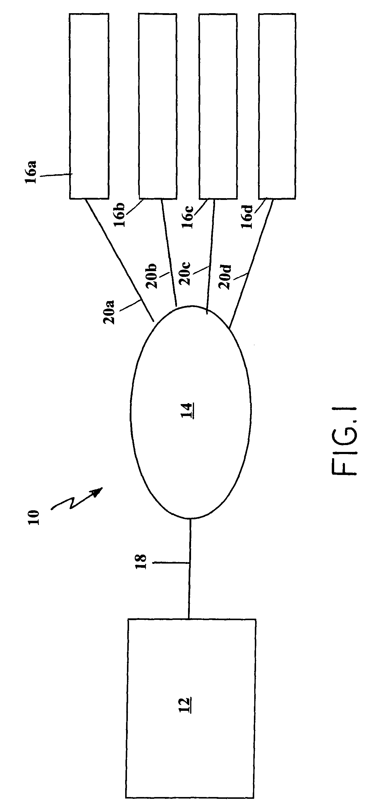
[0015]The laser spark system 10, shown in FIG. 1, has an optical pumping source 12, an optical distributor 14, and a plurality of distinct laser spark generators 16a-16d. The optical pumping source 12 is optically connected to the optical distributor 14 by a first optical fiber 18. The optical distributor 14 is also optically connected to a laser spark generator from the plurality of distinct laser spark generators 16a-16d by an optical fiber from a plurality of distinct laser spark generators 20a-20d, whereby the optical pumping energy can be directed to a single laser spark generator. Therefore, the plurality of distinct laser spark generators 16a-16d are optically pumped from the optical pumping source 12 via the first optical fiber 18, the optical distributor 14, and an optical fiber from the plurality of distinct laser spark generators 20a-20d. The optical fibers (first optical fiber 18 and plurality of distinct laser spark generators 20a-20d) confine the optical pumping energy...


PUM


Abstract

A laser spark distribution and ignition system that reduces the high power optical requirements for use in a laser ignition and distribution system allowing for the use of optical fibers for delivering the low peak energy pumping pulses to a laser amplifier or laser oscillator. An optical distributor distributes and delivers optical pumping energy from an optical pumping source to multiple combustion chambers incorporating laser oscillators or laser amplifiers for inducing a laser spark within a combustion chamber. The optical distributor preferably includes a single rotating mirror or lens which deflects the optical pumping energy from the axis of rotation and into a plurality of distinct optical fibers each connected to a respective laser media or amplifier coupled to an associated combustion chamber. The laser spark generators preferably produce a high peak power laser spark, from a single low power pulse. The laser spark distribution and ignition system has application in natural gas fueled reciprocating engines, turbine combustors, explosives and laser induced breakdown spectroscopy diagnostic sensors.

Description

[0001]The United States Government has rights in this invention pursuant to the employer-employee relationship between the Government and the Inventors.FIELD OF THE INVENTION[0002]A laser spark system providing for the delivery and distribution of optical pumping energy having a low peak power to plural spaced locations to be amplified into a high energy spark.BACKGROUND OF THE INVENTION[0003]Current emission regulations relating to NOx require reciprocating engines to operate at very lean fuel / air mixtures. The excess air keeps the combusting gases cooler and limits thermal NOx development. At the same time, the lean mixture requires much more energy to be delivered to the spark plug for successful ignition. The higher energy flowing through the spark plug electrodes increases erosion to the point that the spark plugs last only hundreds of hours. The spark plugs also cost in excess of $100 each because of the rare earth metals used in the electrodes to extend their life. The result...

Claims


Application Information

Patent Timeline
IPC IPC(8): G02B6/26F02P7/063G02B6/42H01S3/091
CPCF02P23/04F02P7/022G02B6/4296H01S3/094053H01S3/2383H01S3/09415H01S3/113H01S3/2308H01S3/094061
Inventor WOODRUFF, STEVENMCINTYRE, DUSTIN L.
Owner THE UNITED STATES AS REPRESENTED BY THE DEPARTMENT OF ENERGY
Why Eureka
Try Eureka