Transfer case for regenerative hydraulic drive

a technology of regenerative hydraulic drive and transfer case, which is applied in the direction of transportation and packaging, braking systems, etc., can solve the problems of dissipation and waste of kinetic energy carried by the vehicle by virtue of fuel consumption, and achieve the effect of increasing the torque and reducing the motor speed outpu

Active Publication Date: 2008-09-16
BORGWARNER INC
View PDF16 Cites 8 Cited by
  • Summary
  • Abstract
  • Description
  • Claims
  • Application Information

AI Technical Summary

Benefits of technology

[0008]It is a still further object of the present invention to provide a regenerative drive system for a truck tractor having a hydraulic motor and planetary gear assembly which decreases the motor speed output and increases its torque.

Problems solved by technology

The kinetic energy carried by the vehicle which arose by virtue of fuel consumption is dissipated and wasted as it is converted to heat in the brakes of the vehicle.
Mechanically integrating such a system into a large vehicle such as a truck tractor involves many engineering challenges.

Method used


Image

  • Transfer case for regenerative hydraulic drive
  • Transfer case for regenerative hydraulic drive
  • Transfer case for regenerative hydraulic drive

Examples


Embodiment Construction

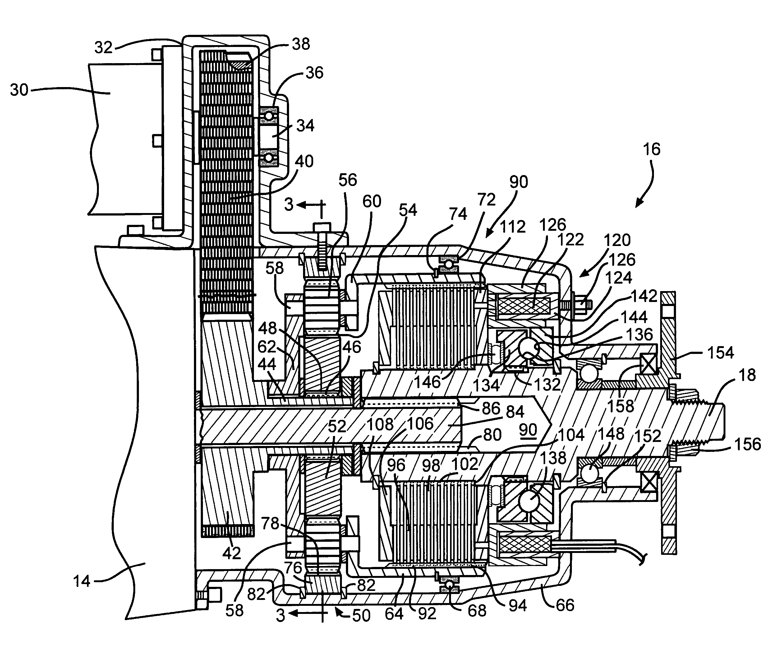
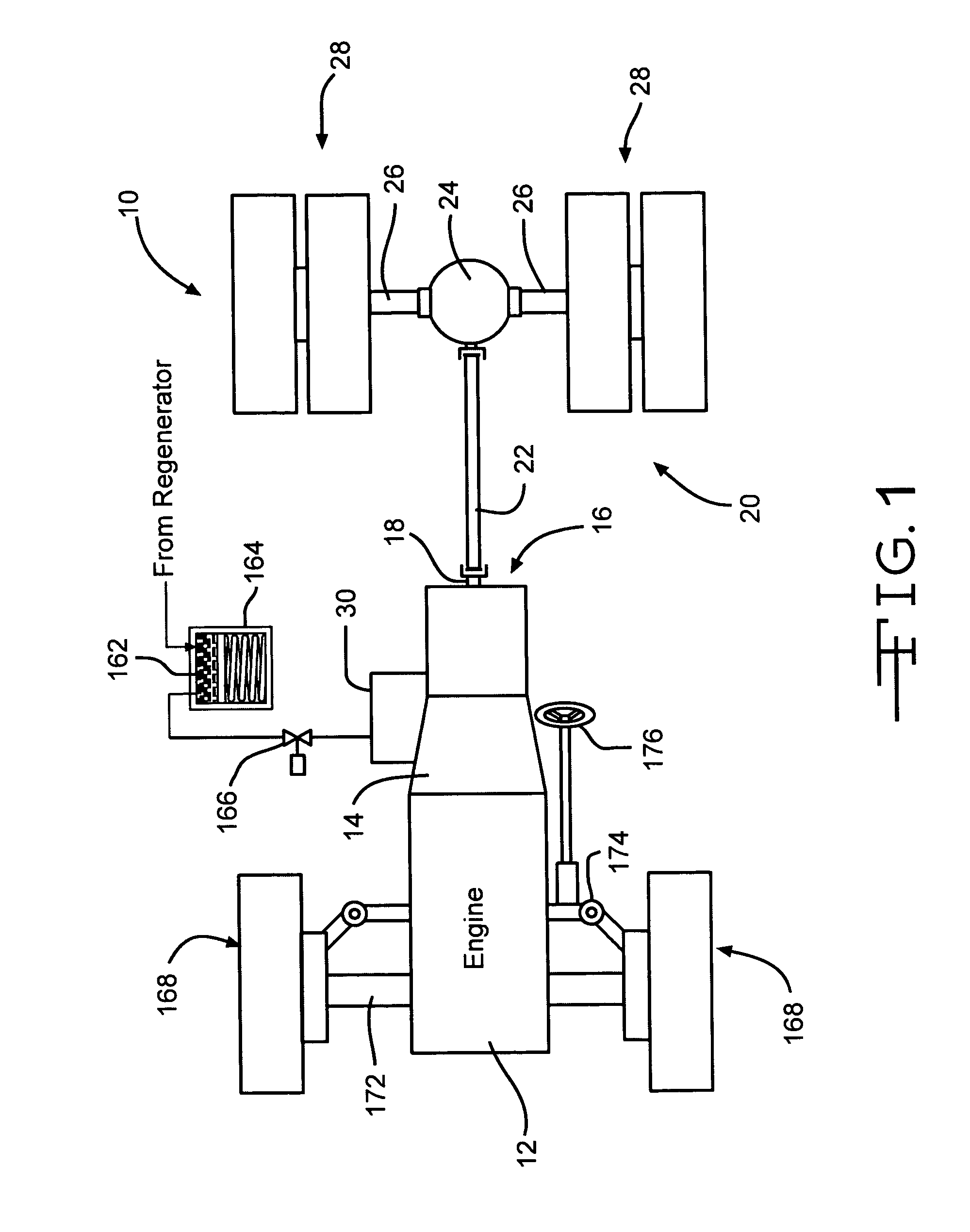
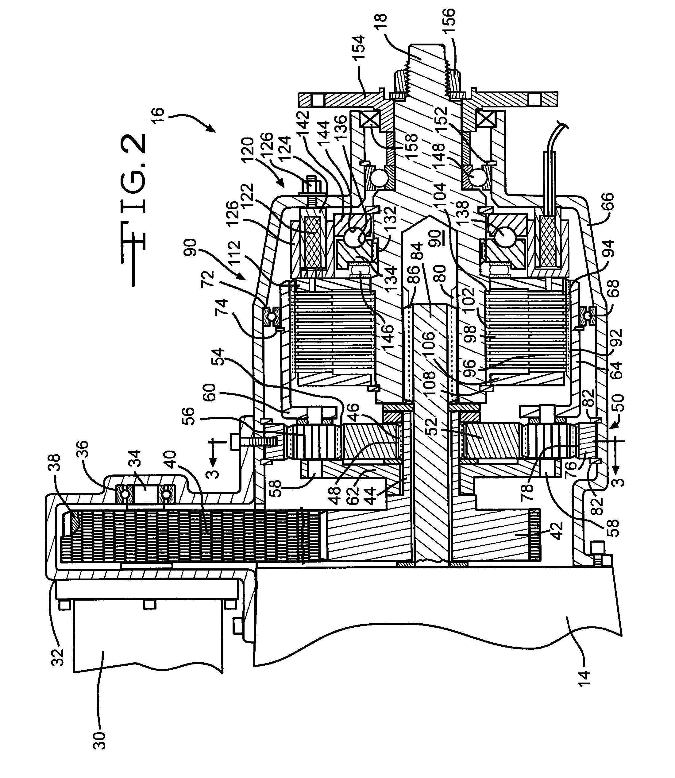
[0013]Referring now to FIGS. 1 and 2, a diagrammatic, plan view of a driveline assembly of a heavy duty truck such as a semi-truck tractor is illustrated and generally designated as the reference number 10. The driveline assembly 10 includes a prime mover 12 such as an internal combustion gas or Diesel engine. The prime mover 12 is directly coupled to and drives a multiple speed automated mechanical transmission (AMT) or manual transmission 14. In turn, the output of the transmission 14 is provided to a transfer case assembly 16. The transfer case assembly 16 is not a conventional transfer case for vehicles such as passenger cars and sport utility vehicles having one input and two outputs. Rather, the transfer case 16 of the present invention includes two inputs and one output which drives only the rear wheels of the driveline assembly 10. The term “transfer case” was chosen to apply to the present device inasmuch as: 1) it is operatively disposed at the output of the vehicle transm...


PUM


Abstract

A regenerative drive system for heavy duty vehicles such as truck tractors having a conventional internal combustion engine and transmission includes a regenerative hydraulic motor and a transfer case. The transfer case has a chain drive coupling the output of the hydraulic motor to the input of a planetary gear speed reduction assembly. The output of the planetary gear assembly is provided to a modulating friction clutch pack which selectively couples the output of the planetary gear assembly to the transmission output and drives the differential and rear vehicle wheels.

Description

TECHNICAL FIELD[0001]The invention relates generally to a unique transfer case for use with a regenerative hydraulic drive and more specifically to a transfer case having a planetary gear speed reduction assembly and a friction clutch pack for use with an auxiliary regenerative hydraulic motor.BACKGROUND OF THE INVENTION[0002]Rapid vehicle acceleration and fuel conservation are two mutually exclusive motor vehicle operating parameters. The steady increase in the cost of fuel has pushed the equation balance point toward fuel conservation in recent time. The desire to reasonably accelerate both passenger cars and trucks, however, has not disappeared. Those conversant with energy conservation acknowledge the most significant fuel consumption or waste occurs when the vehicle is braked to slow or stop it. The kinetic energy carried by the vehicle which arose by virtue of fuel consumption is dissipated and wasted as it is converted to heat in the brakes of the vehicle. This loss of energy...

Claims


Application Information

Patent Timeline
Patent Type & Authority Patents(United States)
IPC IPC(8): F16H37/02
CPCB60T1/093B60W10/02B60W10/04B60W10/06B60W30/18027B60W10/24B60K6/12Y02T10/6208B60W2520/10B60W2540/10F16H2048/04Y02T10/62
Inventor KELLEY, JR., WILLIAM R.
Owner BORGWARNER INC
Why Eureka
Try Eureka