Acoustic liquid dispensing apparatus

a liquid dispensing and acoustic technology, applied in the direction of instruments, heat measurement, specific gravity measurement, etc., can solve the problems of increasing the risk of contamination of the source liquid and/or its deposition interface, increasing the likelihood of contamination, and particularly problematic cross-contamination, etc., to accurately know the distance from the free surface

Active Publication Date: 2008-09-23
LABCYTE
View PDF24 Cites 12 Cited by
  • Summary
  • Abstract
  • Description
  • Claims
  • Application Information

AI Technical Summary

Benefits of technology

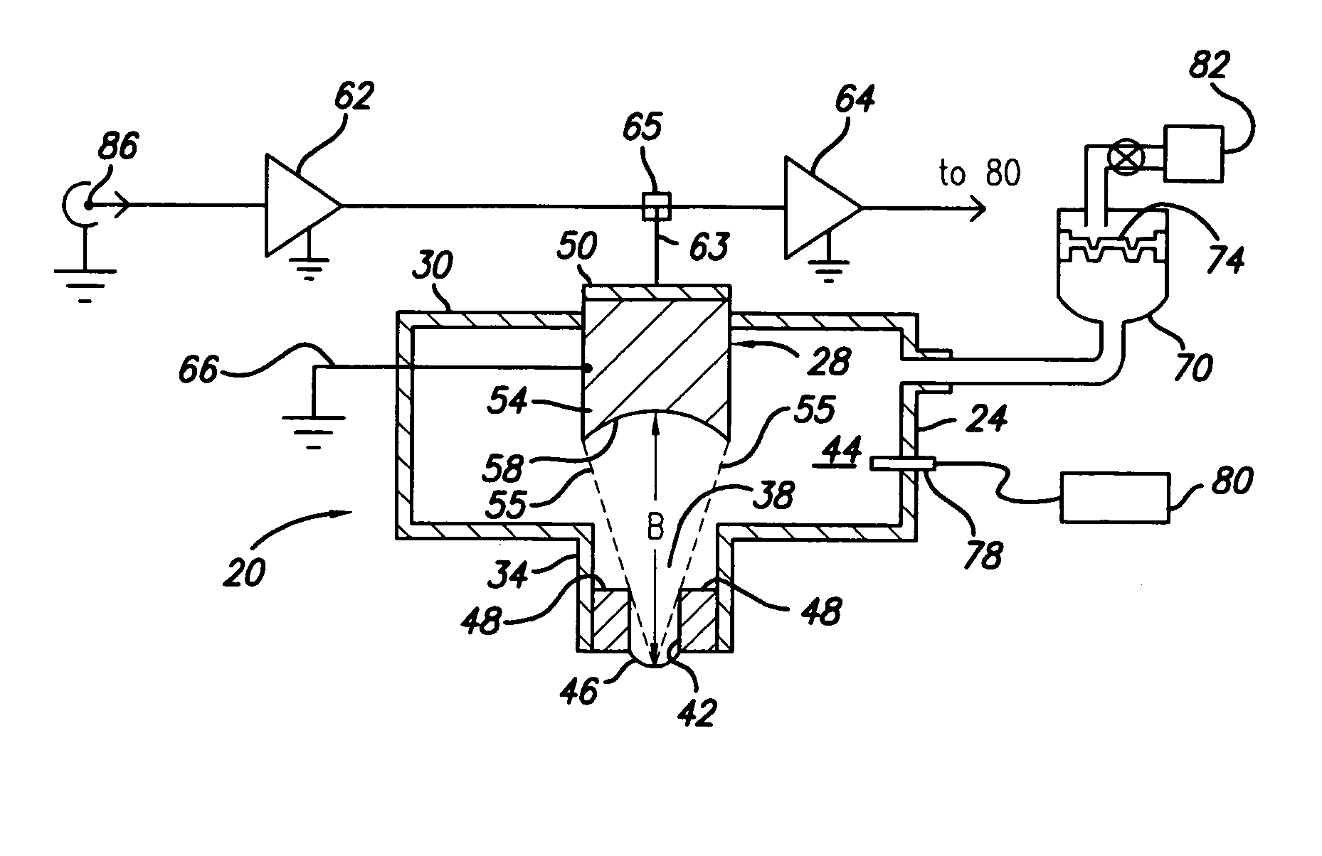
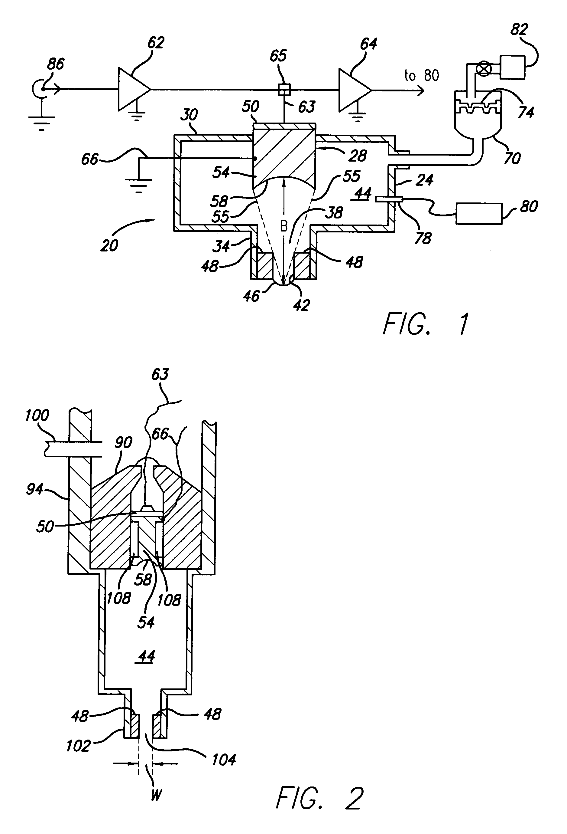
[0014]A pressure adjustment and / or a volume displacement mechanism may also be coupled to the liquid container to adjust the liquid pressure inside the liquid container, and prevent the source liquid from flowing out of the liquid container. The acoustic transducer may be fixed to the body of the container. Alternatively, the acoustic transducer is slidably positioned in relation to the liquid container. A diaphragm or other volume displacement device may be provided within the liquid container to control the liquid pressure within the liquid container. By adjusting the volume displacement device, the level of the liquid at the nozzle may be controlled.
[0016]In another aspect of the invention, a computer and feedback mechanism is provided to control the ejection of droplets of liquids. In order to dispense a precise liquid droplet with the acoustic beam focused on the free surface of the liquid, it is necessary to accurately know the distance from the free surface to the acoustic transducer. This distance can be measured acoustically if the sound velocity in the liquid is known. However, in many applications, the sound velocity is unknown. Furthermore, the sound velocity also may vary with temperature and with changes in concentration. Therefore, in order to put the free surface in focus, it is necessary to measure distance from the lens to the free surface of the liquid. And in order to measure this distance, it is necessary to measure the sound velocity in real time. This can be done by providing a calibration surface to reflect part of the transmitted beam at a known distance. The acoustic transducer may also be adapted to generate a test waveform toward the free surface. The test waveform typically consists of several cycles of sinusoidal wave. In one variation, a calibration surface is provided within the liquid container to reflect part of the focused acoustic beam propagated from the acoustic transducer. Since the distance between the acoustic transducer and the calibration surface is calibrated and known, one may calculate the sound velocity in the source liquid based on the distance and the time interval between the reflected acoustic waves from the lens and the calibration surface. Once the sound velocity in the liquid is known, by detecting the reflected wave back from the free surface of the liquid, the computer may determine the position of the liquid level. Furthermore, knowing the sound velocity in the given source liquid helps one calculate other associated parameters (e.g., concentration, density, viscosity, etc.) of the source liquid.

Problems solved by technology

However, contact printing requires the direct contact of a transfer device with the target surface, thus increasing the risk of contaminating the source liquid and / or its deposition interface.
Cross-contamination is particularly problematic for biotechnology and biopharmaceuticals processes where ultrapure liquid handling and transfer techniques are required.
Liquid transfer methods that require contacting the target surface not only increase the likelihood of contamination, but also decrease the rate of liquid transfer.
This complex machinery may not conveniently and reliably produce high-density arrays.
The mechanical movement of the print head to and from the target surface may increase liquid transfer time and limit system accuracy.
The precision mechanical parts that are necessary to support movement of the print head may also increase system failure rate.
Many biotechnology procedures require high throughput precision transfer of liquid, and have low tolerances for contaminations.
An output nozzle with a small orifice is susceptible to clogging.
This may result in large droplet size and slow liquid droplet ejection rate.
In addition, a mechanical valve may be more prone to clogging and mechanical failure.
However, most of the prior art devices are configured to eject liquid in an upward direction.

Method used


Image

  • Acoustic liquid dispensing apparatus
  • Acoustic liquid dispensing apparatus
  • Acoustic liquid dispensing apparatus

Examples


Embodiment Construction

[0029]The following detailed description should be read with reference to the drawings, in which identical reference numbers refer to like elements through out the different figures. The drawings, which are not necessarily to scale, depict selective embodiments and are not intended to limit the scope of the invention. The detailed description illustrates by way of example, not by way of limitation, the principles of the invention. This description will clearly enable one skilled in the art to make and use the invention, and describes several embodiments, adaptations, variations, alternatives and uses of the invention, including what is presently believed to be the best mode of carrying out the invention.

[0030]Before describing the present invention, it is to be understood that microarray printing is used herein as an exemplary application, and it is not intended to limit the scope of the application. In light of the disclosure herein, one of ordinary skill in the art would appreciat...


PUM


Abstract

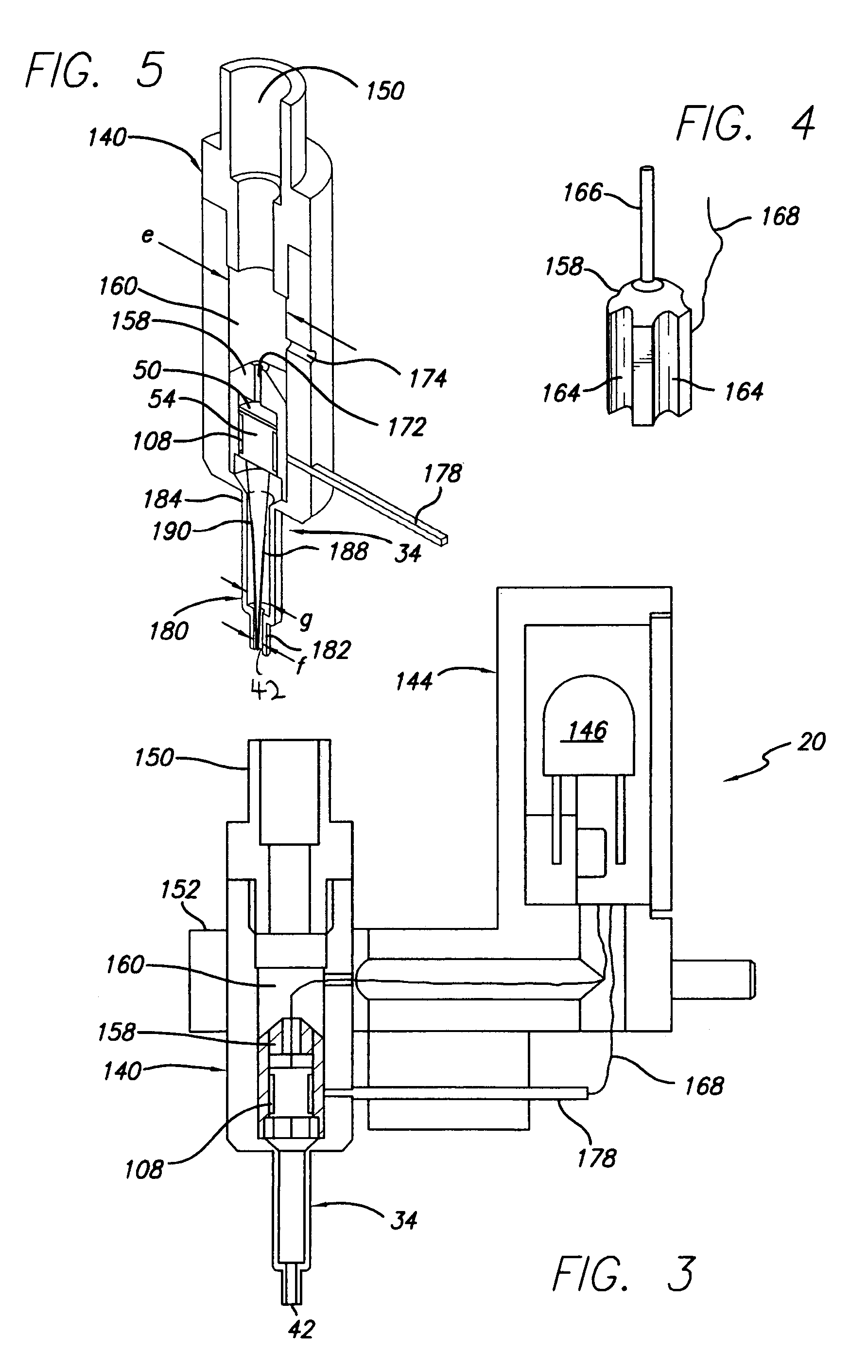
A liquid dispensing apparatus for dispensing droplets of a liquid, and methods for measuring various fluid parameters of the liquid are described. The liquid dispensing apparatus comprises a container having a chamber for holding a liquid. An orifice is positioned at an end of the chamber for dispensing droplets of the liquid, the orifice being configured to retain the liquid in the container if the container is positioned with the orifice facing in a downward direction. An acoustic transducer means is at least partially positioned in the chamber for periodically propagating a focused acoustic beam toward the orifice and through at least some of the liquid while the liquid is contained in the chamber, with the focused acoustic beam being capable of causing a droplet of the liquid to be ejected from the orifice when a free surface of the liquid is within the depth of field of the acoustic transducer means. Fluid parameters that can be measured include the sound velocity in the liquid, liquid level and liquid concentration, liquid acoustic impedance, liquid density and ultrasonic viscosity.

Description

[0001]This application claims the benefit of priority of U.S. Provisional Patent Application 60 / 638,558, filed Dec. 22, 2004, which is incorporated herein by reference.BACKGROUND OF THE INVENTION[0002]1. Technical Field[0003]The present invention relates to small-volume liquid dispensing technology, and more particularly to technology that uses acoustic energy to cause droplets of the liquid to be dispensed.[0004]2. Background Information[0005]Many methods for precision transfer and handling of liquids are known and used in a variety of commercial and industrial applications. A common method for high throughput precision liquid transfer is contact printing / deposition. However, contact printing requires the direct contact of a transfer device with the target surface, thus increasing the risk of contaminating the source liquid and / or its deposition interface. Cross-contamination is particularly problematic for biotechnology and biopharmaceuticals processes where ultrapure liquid handl...

Claims


Application Information

Patent Timeline
Patent Type & Authority Patents(United States)
IPC IPC(8): G01H5/00G01S15/00
CPCG01N29/024G01N29/028G01N29/032G01N29/221G01N29/222G01N29/343G01N9/24G01N11/10G01N2291/044G01N2291/02881G01N2291/02836G01N2291/02809G01N2291/02818
Inventor VAN TUYL, MICHAEL R.CHIAO, JAMESHERRMANN, MICHAEL J.ROSE, ANDREW M.
Owner LABCYTE
Why Eureka
Try Eureka