
Deposited thin films and their use in separation and sacrificial layer applications

a technology of deposited thin films and sacrificial layers, applied in the direction of chemical vapor deposition coatings, vacuum evaporation coatings, packaged goods types, etc., can solve the critical disadvantage of needing top and bottom alignment, hampered material use, lack of uniformity and controllability, etc., and achieve high performance

Inactive Publication Date: 2008-09-23
PENN STATE RES FOUND
View PDF53 Cites 27 Cited by
  • Summary
  • Abstract
  • Description
  • Claims
  • Application Information

AI Technical Summary

Benefits of technology

[0034]Another approach to utilizing the high performance structures that can be created on plastic laminates with the separation approach of the present invention is to dice the individual device-containing islands of t

Problems solved by technology

However, the use of the material is hampered due to the following: its lack of uniformity and controllability, the necessity of having electrical conduction paths for the electrochemical etching required to create the material, the fact that it must be formed on a conductor, and the residual impurities left in the material after its electrochemical etching.
However, it requires anodic or direct (fusion) bonding and has the critical disadvantage of needing alignment of top and bottom.
This makes the fabricating of small channel dimensions difficult because of misalignment of the two substrates and micro void formation at the bonding interface during the bonding process.
Since it is based on sacrificial layer use, it can produce channel dimensions down to a few nanometers although to date the sacrificial layer removal step has been a relatively complex process (M. J. de Boer, W. Tjerkstra et al., J. of Microelectrochemical systems, Vol. 9, No. 1, pp.

Method used


Image

  • Deposited thin films and their use in separation and sacrificial layer applications
  • Deposited thin films and their use in separation and sacrificial layer applications
  • Deposited thin films and their use in separation and sacrificial layer applications

Examples


Embodiment Construction

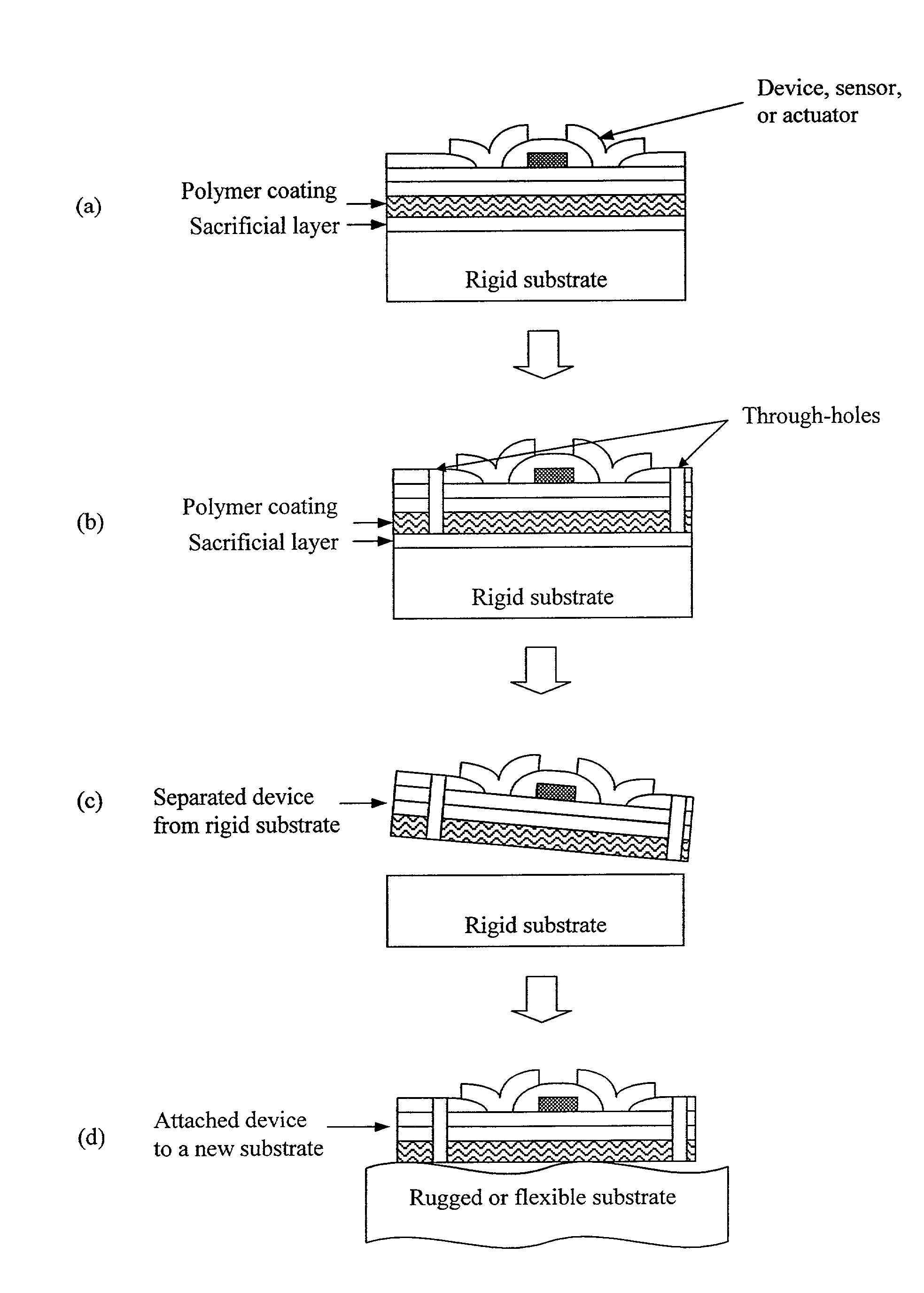
[0088]The approach to producing materials with large void volumes and therefore large surface area to volume ratios in the present invention is to use deposition to grow as-deposited porous films In the present invention, void regions (pore) are reasonably uniform through the thickness of the film and across the film. The process for deposition is unique because it is performed at low temperature, the present inventors have demonstrated that the present invention can be used to control void size and void fraction, the void-column network morphology does not vary over thicknesses of interest, the columns can be polycrystalline or amorphous material. Plasma approach including dc and rf discharge, sputting and high density plasma tools can be used to control the interaction between deposition and etching during growth. The process, demonstrated using high density plasma deposition etching interaction, is able to give high porosity (of up to approximately 90%), controlled pore size mate...


PUM

PropertyMeasurementUnit
Widthaaaaaaaaaa
Heightaaaaaaaaaa
Temperatureaaaaaaaaaa

Abstract

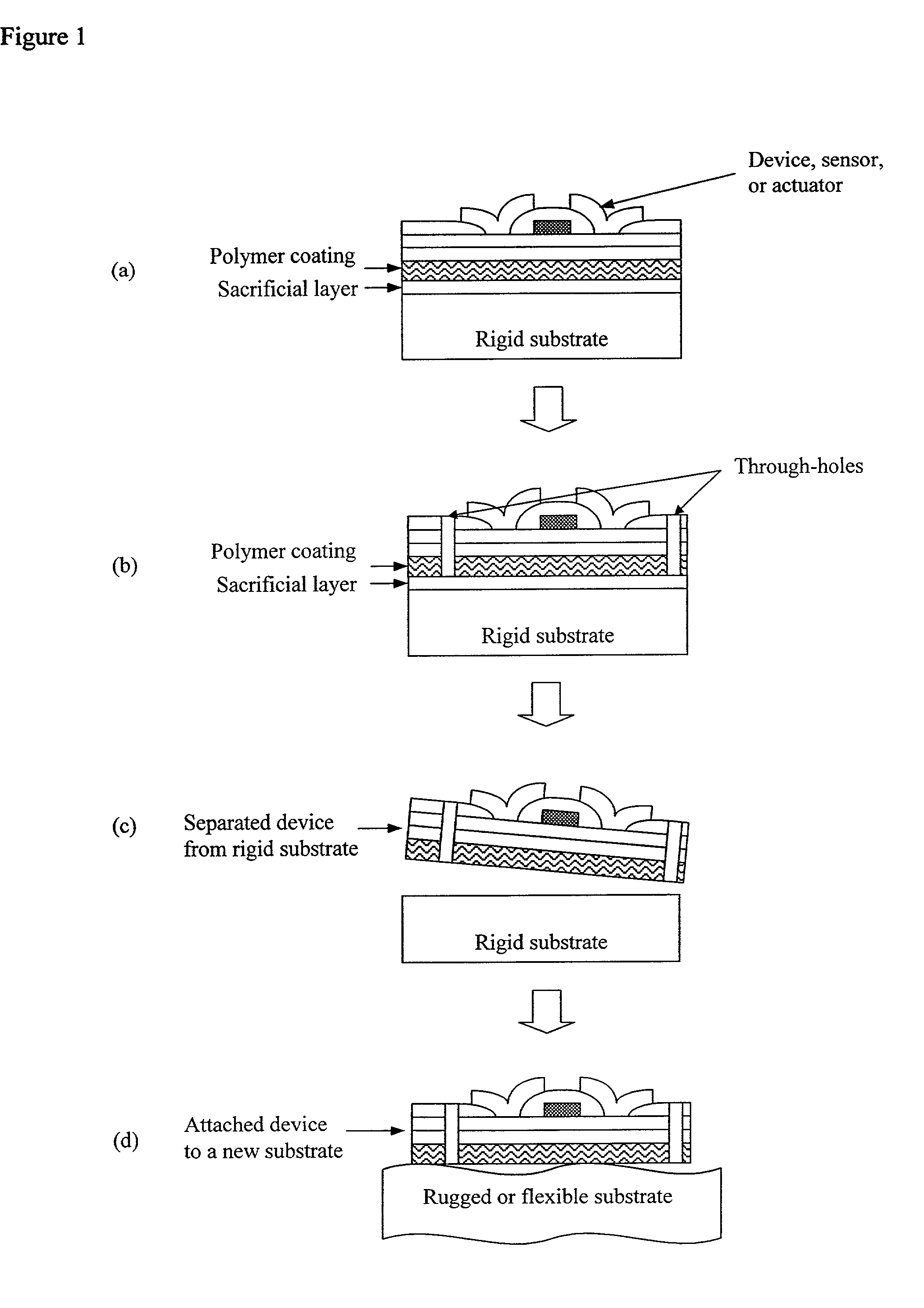
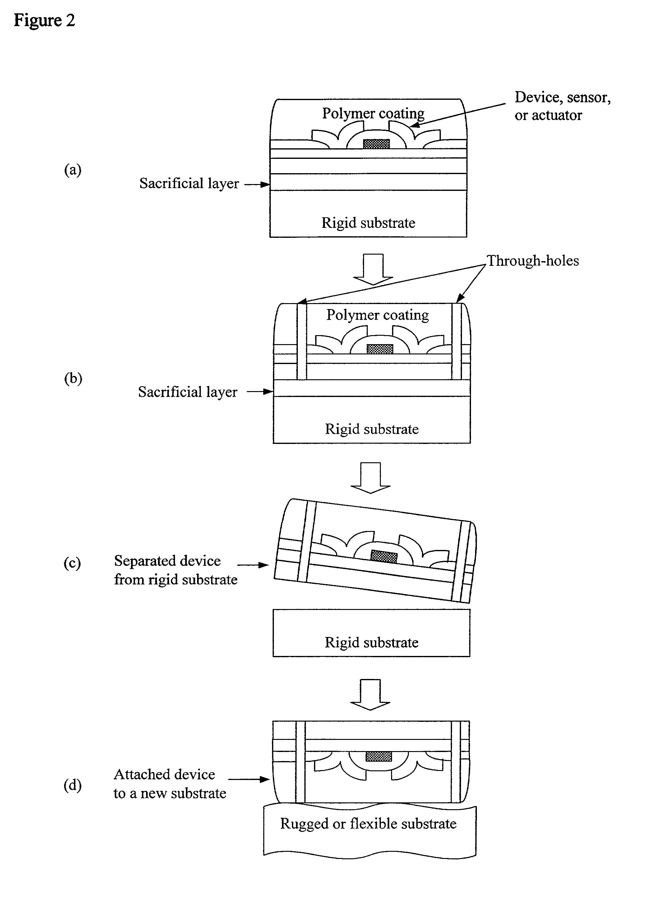
This invention uses large surface to volume ratio materials for separation, release layer, and sacrificial material applications. The invention outlines the material concept, application designs, and fabrication methodologies. The invention is demonstrated using deposited column / void network materials as examples of large surface to volume ratio materials. In a number of the specific applications discussed, it is shown that it is advantageous to create structures on a laminate on a mother substrate and then, using the separation layer material approach, to separate this laminate from the mother substrate using the present separation scheme. It is also shown that the present materials have excellent release layer utility. In a number of applications it is also shown how the approach can be used to uniquely form cavities, channels, air-gaps, and related structures in or on various substrates. Further, it is demonstrated that it also can be possible and advantageous to combine the schemes for cavity formation with the scheme for laminate separation.

Description

[0001]This application claims the benefit of U.S. Provisional Application No. 60 / 201,937 filed May 5, 2000; U.S. Provisional Application No. 60 / 197,548 filed Apr. 17, 2000; U.S. Provisional Application No. 60 / 208,197 filed May 31, 2000; U.S. Provisional Application No. 60 / 215,538 filed Jun. 30, 2000; U.S. Provisional Application No. 60 / 231,626 filed Sep. 11, 2000 and U.S. Provisional Application No. 60 / 268,208 filed Feb. 12, 2001; U.S. Provisional Application No. 60 / 235,794 filed Sep. 27, 2000; U.S. patent application Ser. No. 09 / 739,940 filed Dec. 19, 2000; now U.S. Pat. No. 6,794,196 and U.S. patent application Ser. No. 09 / 580,105 filed May 30, 2000, now U.S. Pat. No. 6,399,177 the contents of all are hereby incorporated by reference into this application.[0002]U.S. Provisional Application No. 60 / 172,840 filed Dec. 20, 1999 claimed in U.S. patent application No. 09 / 739,940 was made with government support under the grant F33615-98-1-5166 415-37; 773A from the Defense Advanced Rese...

Claims


Application Information

Patent Timeline
IPC IPC(8): H01L21/00B81B3/00B81C1/00G01N21/17G01N27/447
CPCB81C1/00119B81C1/0038B81C1/00476G01N21/17G01N27/44717Y10T29/49108B81C2201/0115
Inventor FONASH, STEPHEN J.NAM, WOOK JUNLEE, YOUNGCHULCHANG, KYUHWANHAYES, DANIEL J.KALKAN, A. KAANBAE, SANGHOON
Owner PENN STATE RES FOUND
Learn More