Exhaust heat recovery system
a heat recovery and exhaust technology, applied in the field of exhaust heat recovery systems, can solve problems such as energy waste, and achieve the effect of increasing the recovery rate of heat energy and the amount of electric energy generated
- Summary
- Abstract
- Description
- Claims
- Application Information
AI Technical Summary
Benefits of technology
Problems solved by technology
Method used
Image

Examples
first embodiment
[0032]Note that, the same reference numerals are used to denote structural members of the different embodiments that are the same, and repeated description thereof is omitted. The explanation will begin by focusing on the invention.
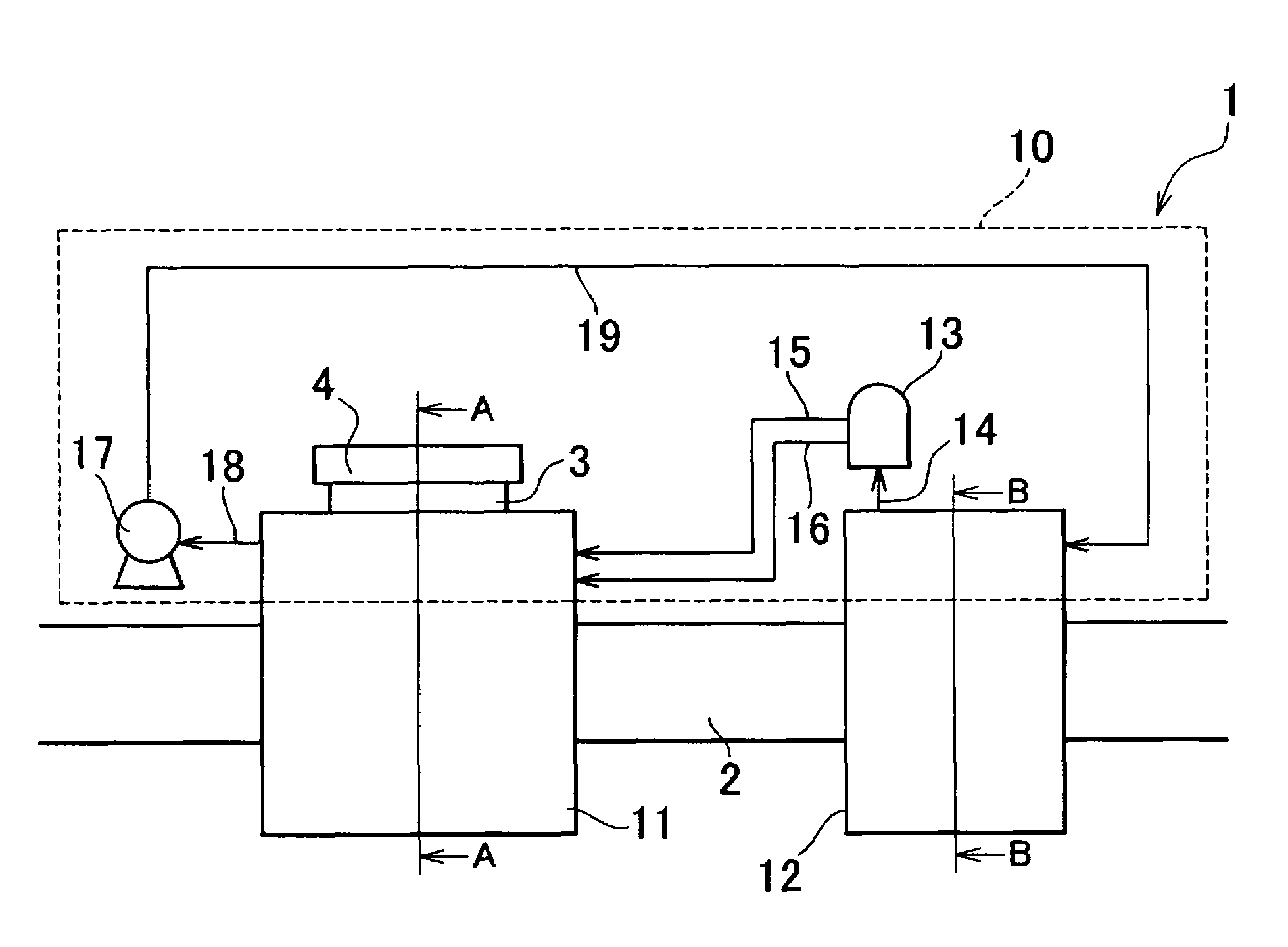
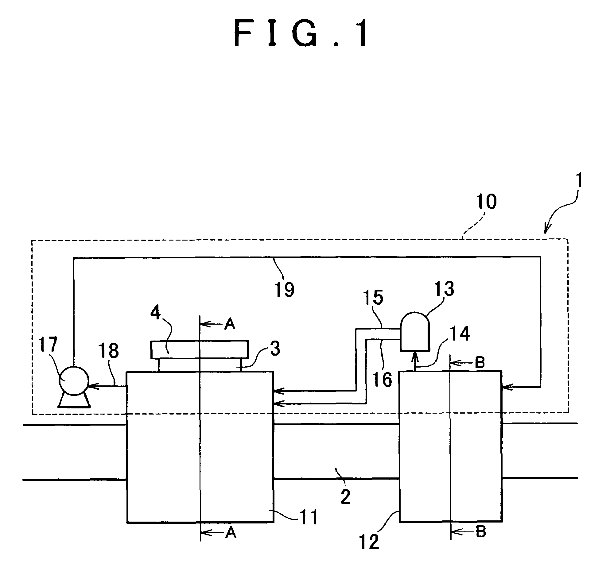
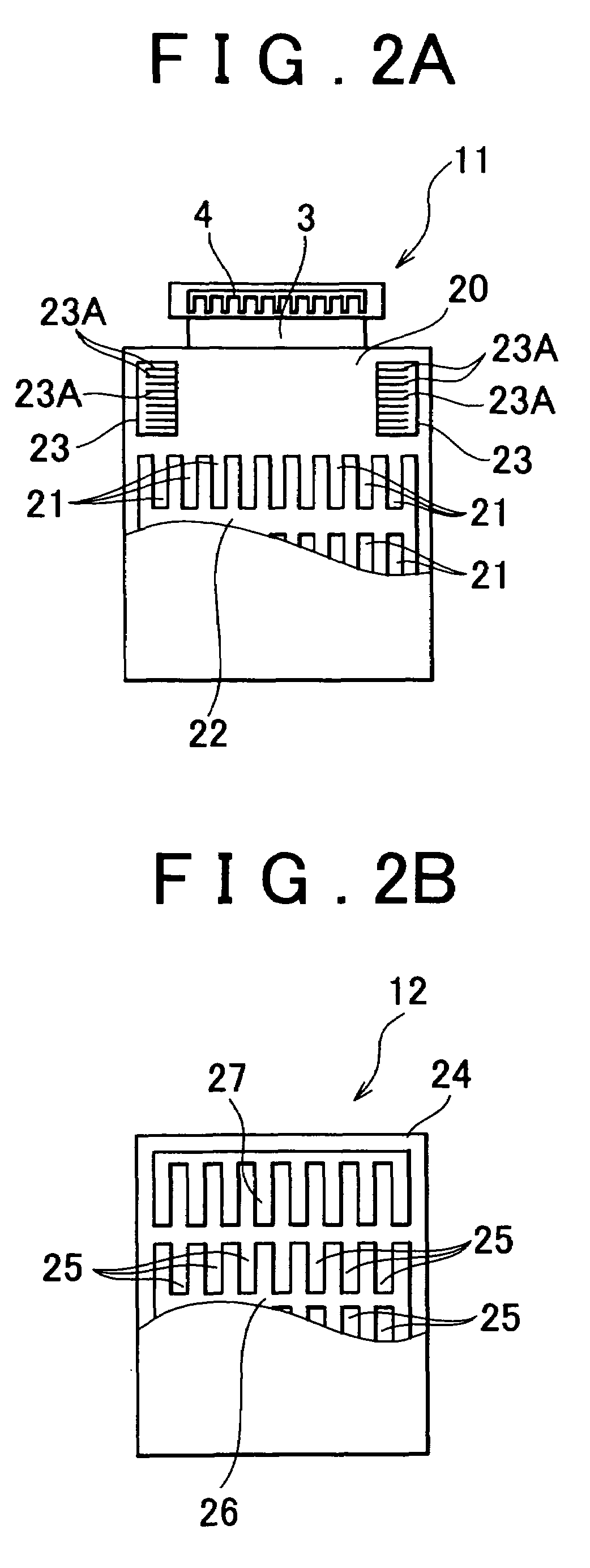
[0033]FIG. 1 shows the configuration of an exhaust heat recovery system 1 according to a first embodiment of the invention; and FIGS. 2A and 2B show respective cross-sectional views along lines A-A and B-B of FIG. 1.
[0034]An exhaust heat recovery system 1 according to the first embodiment, as shown in FIG. 1, is provided with an exhaust gas passage 2 that is connected to an engine, not shown, that acts as a heat source. Exhaust gas that is discharged from the engine passes along the exhaust gas passage 2. A chemical heat pump (hereinafter referred to as simply “heat pump”) 10 is provided in the exhaust gas passage 2. The heat pump 10 includes a heat generation unit 11 and a heat recovery unit 12. The heat generation unit 11 is positioned toward the upstre...
second embodiment
[0063]Next, the operation and effects of the above-described exhaust heat recovery system 5 will be explained.
[0064]In the exhaust heat recovery system 5 according to the second embodiment, the exhaust gas that is discharged from the engine, not shown, flows through the exhaust gas passage 2. Note that, the exhaust gas that flows through the exhaust gas passage 2 passes through the catalyst 34 formed in the catalyst storage unit 31, and then through the second exhaust gas passageways 26 formed in the heat recovery unit 12.
[0065]The exhaust gas that flows along the exhaust gas passage 2 is purified as it passes through the catalyst 34, and then discharged from the vehicle via a muffler, not shown. However, if the temperature of the catalyst 34 is low, the catalyst 34 is not adequately warmed-up, and thus its purification performance is impaired. To address this problem, the temperature sensor 35 is provided for the catalyst 34. Accordingly, the temperature of the catalyst 34 can be ...
third embodiment
[0072]In the exhaust heat recovery system 6 the separator 13 is connected to the exothermic reaction portion 23 of the heat generation unit 11 shown in FIG. 6A via second and third gas passages 41 and 42. More specifically, hydrogen flows along the second gas passage 41, and acetone flows along the third gas passage 42. Further, respective first and second switching valves 43 and 44 are provided at positions along the second and third gas passages 41 and 42. The first and second switching valves 43 and 44 correspond to a selection portion of the invention. By switching the first and second switching valves 43 and 44, namely, the selection means or the selection portion, it is possible to select the supply destination of the heat, namely, which one of the thermoelectric conversion module 3 and the catalyst 34 is supplied with heat.
[0073]The first and second switching valves 43 and 44, as well as being provided in the second and third gas passages 41 and 42, are connected to respecti...
PUM
 Abstract
Description
Claims
Application Information
 - R&D
- Intellectual Property
- Life Sciences
- Materials
- Tech Scout
- Unparalleled Data Quality
- Higher Quality Content
- 60% Fewer Hallucinations
Browse by: Latest US Patents, China's latest patents, Technical Efficacy Thesaurus, Application Domain, Technology Topic, Popular Technical Reports.
© 2025 PatSnap. All rights reserved.Legal|Privacy policy|Modern Slavery Act Transparency Statement|Sitemap|About US| Contact US: help@patsnap.com