Fuel/air premixer for gas turbine combustor

a technology of gas turbine combustor and fuel/air premixer, which is applied in the direction of turbine/propulsion fuel valve, machine/engine, light and heating apparatus, etc. it can solve the problems of uneven fuel concentration distribution, damage to premixing tubes, and damage to fuel atomizer nozzles, so as to reduce the likelihood of blockage in the passage, reduce the likelihood of weight, and low fuel injection pressure

Inactive Publication Date: 2008-10-14
JAPAN AEROSPACE EXPLORATION AGENCY
View PDF12 Cites 93 Cited by
  • Summary
  • Abstract
  • Description
  • Claims
  • Application Information

AI Technical Summary

Benefits of technology

[0014]An object of the present invention is to provide a novel fuel / air premixer for a gas turbine combustor wherein an airblast atomizer nozzle comprising a liquid film-forming body, in which a conventional tubular inner surface serves as a fuel liquid film-forming surface, is disposed at an inlet portion to a premixing tube as fuel atomizing means. When fuel from a tip end of the liquid film-forming body is atomized by an air stream and mixed with air, air stream swirling means which are effective in forming a favorable mixture are used to increase the velocity of the air stream passing through the inside of the liquid film-forming body and form a flow which spreads outward in a radial direction, thereby improving the atomization performance and mixing performance such that both complete combustion and very low NOx combustion can be achieved easily. As a result, back flows within the premixing tube and reductions in the mixture velocity in a central portion of the premixing tube are suppressed, burning damage to components such as the premixing tube is prevented in cases of backfiring caused by abnormal decreases in the air stream velocity and so on, and when the air velocity recovers, the flame which backfired is immediately discharged downstream from the premixing tube.

Problems solved by technology

The nitrogen oxide NOx (NO and NO2) that is discharged from various combustion devices is not only harmful to the human body, but is also a cause of acid rain and the greenhouse effect, and as a result has become subject to official emission controls in industrialized nations.
The technical aspect to this is that it is far more difficult to form a pre-mixture with a high degree of homogeneity when using liquid fuel than when using gaseous fuel.
When the temperature and pressure of the air are high, a chemical reaction may occur in the aforementioned process, possibly leading to auto-ignition.
If, as a result of this auto-ignition, a flame is formed within the premixing tube and held within the interior of the tube, the premixing tube, fuel atomizer nozzle, and so on are damaged by burning.
When fuel particle dispersal is insufficient, the fuel concentration distribution remains uneven over the cross section of the premixing tube outlet even if the fuel particles are completely vaporized.
It is particularly difficult to avoid this unevenness when the diameter of the premixing tube is large.
However, a problem which arises when forming a swirl within the premixing tube is that regions with a low velocity are typically formed in the vicinity of the central axis such that when the swirl is strong, a back flow is formed.
This increases the likelihood of so-called backfiring, in which a flame runs up through these regions within the premixing tube from the combustion chamber.
If, in a premixing tube taking the form of a venturi tube, the air stream is caused to swirl in order to promote dispersion of the fuel particles and mixing of the fuel vapor and air, a back flow region is formed on the central axis of the enlarged portion, increasing the likelihood of backfiring.
This problem can be solved by bundling together a large number of prevaporizing tubes with small passage cross sections, but this solution leads to further problems such as complication of the fuel supply system, weight increases, and so on.
Since fuel also exists in this part, backfiring is likely to occur.
The problem with this type of fuel / air premixer for a gas turbine combustor is that a flame is formed at the outlet of the premixing tube, and hence the tip end portion of the central body is heated excessively by the flame and radiation from the flame.
If the tip end of the central body is positioned upstream of the premixing tube outlet in an effort to suppress such excessive heat, the end of the back flow region, which had been positioned downstream of the premixing tube outlet, moves within the premixing tube, and hence the vicinity of the premixing tube outlet may be heated excessively.
Moreover, the very existence of the central body wastes space and increases weight, and since the central body is supported by vanes of the air swirler attached to the inlet portion of the premixing tube, thus forming a so-called cantilever structure, there is a danger of the central body falling off due to combustion vibration or the like.

Method used


Image

  • Fuel/air premixer for gas turbine combustor
  • Fuel/air premixer for gas turbine combustor
  • Fuel/air premixer for gas turbine combustor

Examples


Embodiment Construction

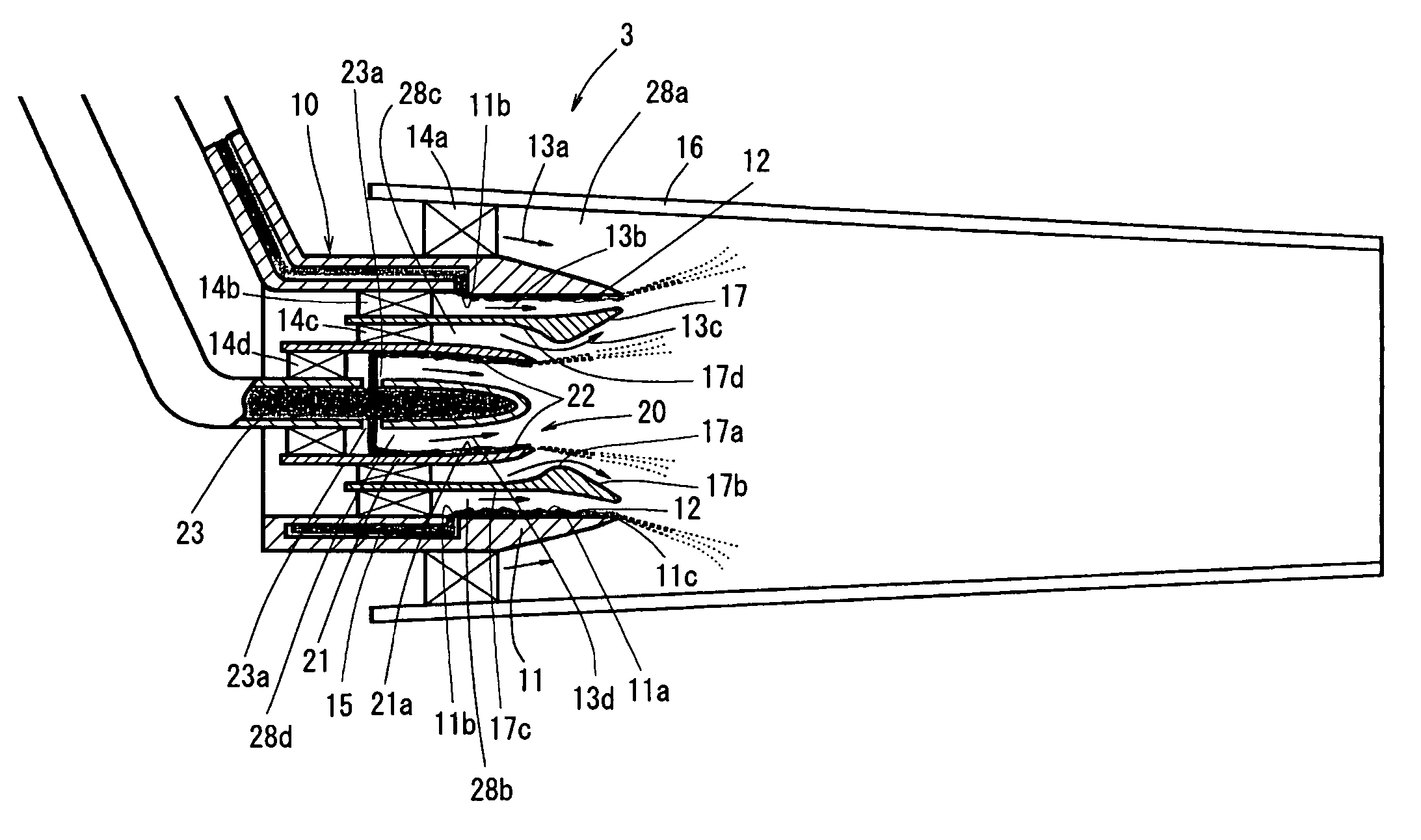
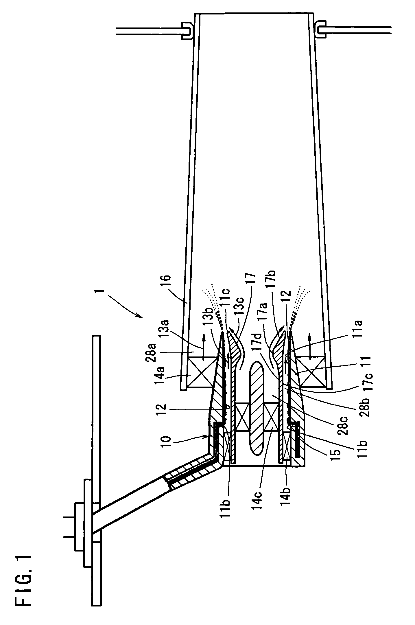
[0036]FIG. 1 is a longitudinal sectional view showing a first embodiment of a fuel / air premixer for a gas turbine combustor according to the present invention. In a fuel / air premixer 1 for a gas turbine combustor shown in FIG. 1, an airblast atomizer nozzle 10 is provided as fuel atomizing means at an inlet portion to a tubular premixing tube 16. A flow-deflecting tubular body 17 having an annular cross section is disposed on the inside of and coaxially with a liquid film-forming body 11 of the airblast atomizer nozzle 10. A first air swirler 14b is disposed at an upstream portion of a first annular passage 28b between an outer peripheral surface 17c of the flow-deflecting tubular body 17 and a liquid film-forming surface 11a of the liquid film-forming body 11, and a second air swirler 14c is disposed at an upstream portion of a second annular passage 28c having as a wall surface an inner peripheral surface 17d of the flow-deflecting tubular body 17. The flow-deflecting tubular body...


PUM


Abstract

A fuel / air premixer for use in a gas turbine improves the atomization performance and mixing performance of the fuel by guiding an air so as to flow in an outward radial direction. A flow-deflecting tubular body having an annular cross section is disposed on the inside of and coaxially with a liquid film-forming body of an airbiast atomizer nozzle disposed at the inlet portion of a premixing tube. The outer peripheral surface of the flow-deflecting tubular body has a wall surface which increases in outer diameter toward the tip end of a first annular passage. The inner peripheral surface of the flow-deflecting tubular body has a form in which the inner diameter has a minimum to form a contracted portion, and then increases dramatically toward the tip end.

Description

BACKGROUND OF THE INVENTION[0001]1. Field of the Invention[0002]The present invention relates to a fuel / air premixer used in a premixed, prevaporized-type combustor of a gas turbine which uses liquid fuel, and more particularly to a fuel / air premixer for a gas turbine combustor having at least one airblast atomizer nozzle comprising a liquid film-forming body disposed at an inlet portion of a premixing tube.[0003]2. Description of the Prior Art[0004]The nitrogen oxide NOx (NO and NO2) that is discharged from various combustion devices is not only harmful to the human body, but is also a cause of acid rain and the greenhouse effect, and as a result has become subject to official emission controls in industrialized nations. Gas turbines are no exception to these controls, and NOx emission standards are provided for gas turbines on national and local levels for industrial use, and on an international level for aircraft use. These emission standards appear likely to be strengthened in t...

Claims


Application Information

Patent Timeline
Patent Type & Authority Patents(United States)
IPC IPC(8): F02C1/00F02C7/232F23D11/10F23R3/14F23R3/28F23R3/32
CPCF23D11/107F23R3/286F23R3/32F23D2900/11101F23R3/14
Inventor HAYASHI, SHIGERU
Owner JAPAN AEROSPACE EXPLORATION AGENCY
Why Eureka
Try Eureka