Methods of fabricating a membrane with improved mechanical integrity

a technology of mechanical integrity and membrane, applied in the manufacture/assembly of piezoelectric/electrostrictive devices, electrical apparatus, electrical devices, etc., can solve the problems of device literally falling apart, discontinuous film growth, etc., to reduce the height of the step or edge, and reduce the negative effect of electrode steps or edges

Inactive Publication Date: 2008-10-14
AVAGO TECH INT SALES PTE LTD
View PDF79 Cites 9 Cited by
  • Summary
  • Abstract
  • Description
  • Claims
  • Application Information

AI Technical Summary

Benefits of technology

[0010]Methods for fabricating robust films across a patterned underlying layer's edges or steps are disclosed. The novel methods diminish the negative effects of electrode steps or edges on the integrity of a membrane. Thus, the methods are particularly applicable to membrane release technology. The height of the step or edge is eliminated or reduced to increase the mechanical integrity of the film.
[0012]In another embodiment, a single large electrode step is made into smaller multiple steps by depositing multiple layers of selectively etchable materials. Subsequent cycles of etching lead to a “staircase” with a lessening of the detrimental material weakening.

Problems solved by technology

The piezoelectric film typically extends across the edges of this patterned base electrode, but film growth tends to be discontinuous in these regions.
If attempts are made to fabricate a freestanding membrane from such a segmented film, the cracks at these discontinuities cause the membrane—and the device—to literally fall apart.

Method used


Image

  • Methods of fabricating a membrane with improved mechanical integrity
  • Methods of fabricating a membrane with improved mechanical integrity
  • Methods of fabricating a membrane with improved mechanical integrity

Examples


first embodiment

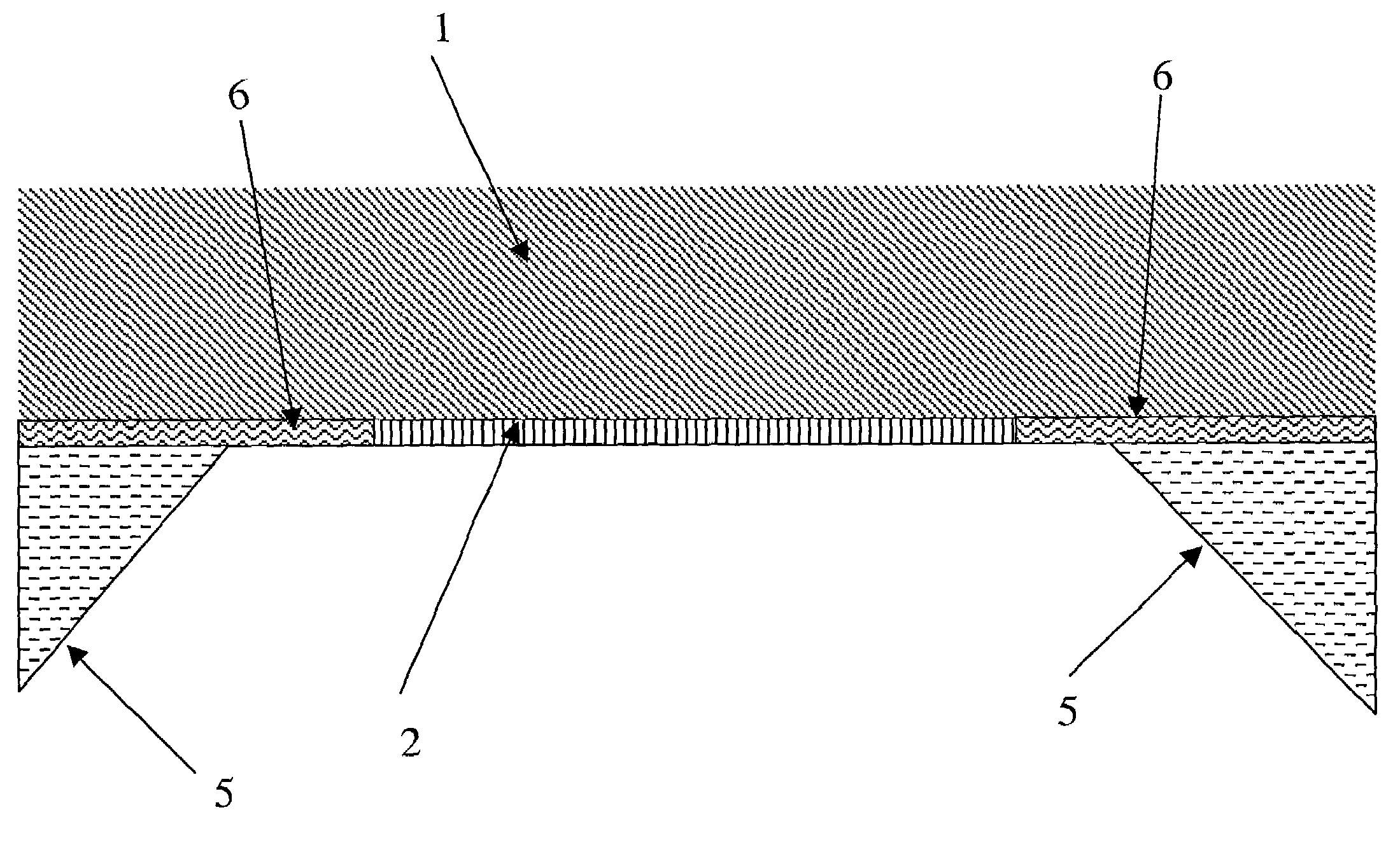
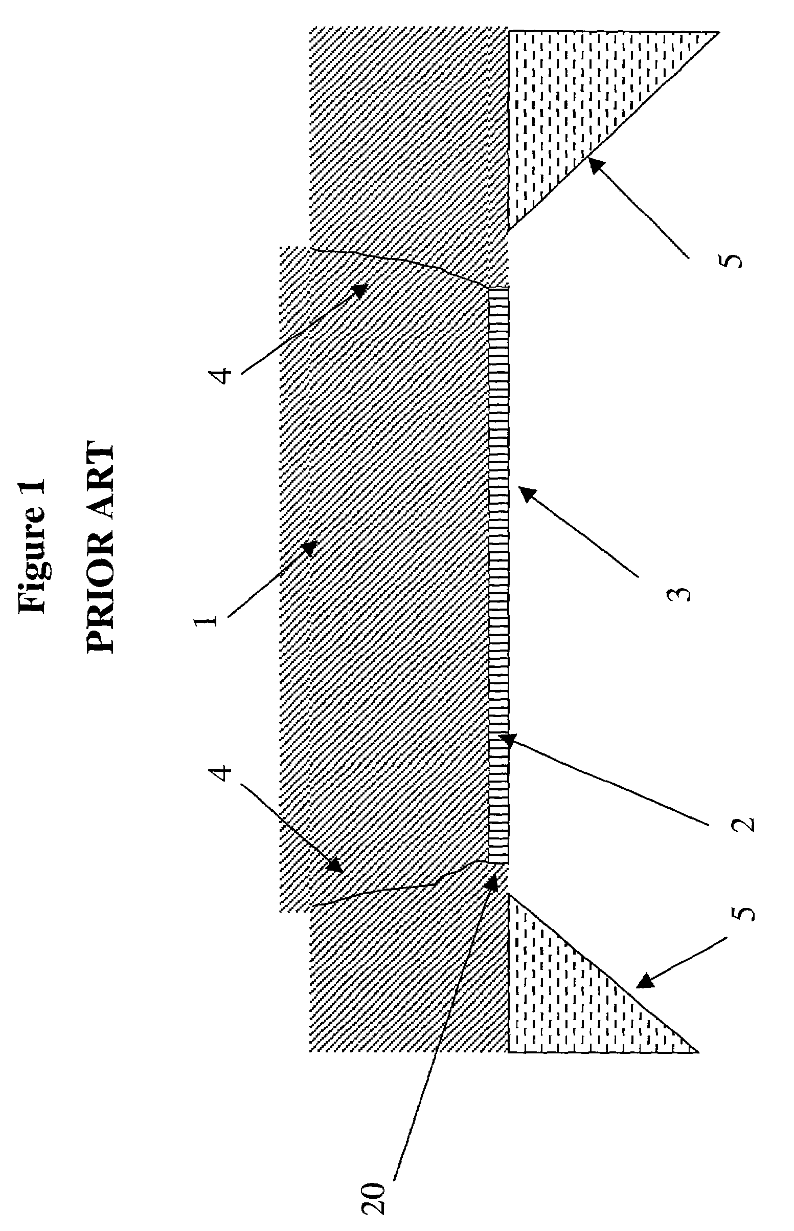
[0052]In the invention, the elimination of the edge through placement of a material adjacent to the base electrode of equal or comparable height is achievable through multiple processes. These processes include chemical mechanical polishing (CMP) planarization, polymer planarization, and polymer reflow with liftoff In each process, the height of the step or edge (20) from FIG. 1 is eliminated or reduced through placement of a material adjacent to the electrode (2) of equal or comparable height.

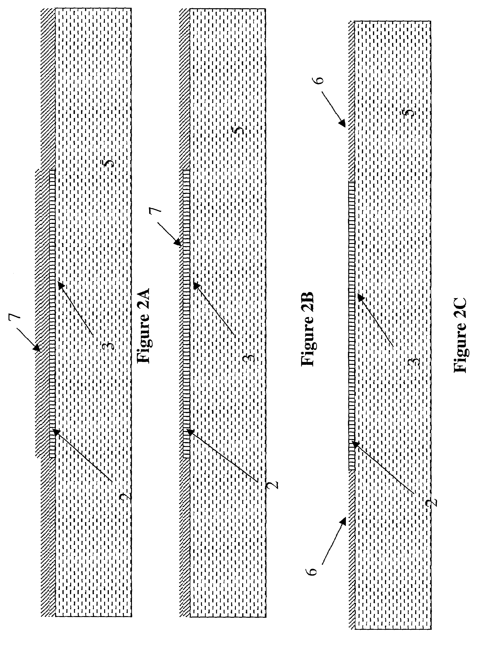
[0053]FIGS. 2A through 2C illustrate the generic planarization process. First, a sacrificial film (7) roughly twice the thickness of the electrode is deposited over the patterned electrode (2), resulting in FIG. 2A. Preferred metals for the electrode (2) include aluminum and titanium, but may be any suitably conducting element or compound. The sacrificial film (7) is a non-conductive material, preferably with a low dielectric constant. Although the preferred material for this film is SiO2, oth...

third embodiment

[0081]In the invention, a continuously smoothed dome is achieved through specific use of lithography, deposition and etching steps. The doming decreases the effects of the edge of the electrode on membrane integrity. It is accomplished by melting or reflowing resist with solvent into a drop shape. The resist and material underneath it are then simultaneously etched and the shape is thus transferred.

[0082]FIGS. 7A through 7D are an illustration of the process steps for producing a continuously smoothed dome electrode.

[0083]This technique is based upon development of a process such that, for a selected etchant, the resist and masking material will have comparable etch rates. Under these circumstances, as the etch proceeds the resist's vertical profile will be mimicked in the electrode profile. For example, if the electrode (2) and resist removal rate are equal the vertical profile of the resist will be exactly reproduced in the electrode (2) beneath the resist. If however the resist i...

fourth embodiment

[0088]FIGS. 8A-8I show a fourth embodiment where the electrode is patterned as a final step in the process instead of during the initial steps.

[0089]In this embodiment, a very thin layer of a non-conducting material (21) is deposited on a substrate (8). The non-conducting material (21) has a low dielectric constant. Preferable non-conducting materials (21) include SiO2 and SiN. The substrate (8) is preferably Si or GaAs. The resulting wafer is shown in FIG. 8A.

[0090]The thin, non-conducting material (21) is first patterned into the shape desired for the patterned electrode in the finished device. This step results in the wafer shown in FIG. 8B.

[0091]Then, a first layer (22) of metal is deposited everywhere. Subsequently, a second layer (23) of a different metal is deposited. These two layers (22) and (23) preferably are Ti and Al, respectively, and while left unpatterned at this point, will ultimately form the patterned base electrode. Subsequently, a layer (24) of piezoelectric mat...


PUM

PropertyMeasurementUnit
thicknessaaaaaaaaaa
thicknessaaaaaaaaaa
temperatureaaaaaaaaaa

Abstract

Methods for fabricating robust films across a patterned underlying layer's edges or steps are disclosed. The novel methods diminish the negative effects of electrode steps or edges on the integrity of a membrane. Thus, the methods are particularly applicable to membrane release technology. The height of the step or edge is eliminated or reduced to increase the mechanical integrity of the film.

Description

BACKGROUND OF THE INVENTION[0001]1. Field of the Invention[0002]The invention pertains to the field of membrane release technology. More particularly, the invention pertains to the fabrication of membranes with improved mechanical integrity.[0003]2. Description of Related Art[0004]Thin film resonators (TFRs) are thin film acoustic devices which can resonate in the radio frequency (RF) to microwave range, for example, 0.5 to 5 Gigahertz (GHz), in response to an electrical signal. A typical TFR has a piezoelectric film between a first electrode and a second electrode which apply an electric field to the piezoelectric film. The film is made of a piezoelectric crystalline material, such as zinc oxide, aluminum nitride (AlN) or other piezoelectric crystalline material, which exhibits a piezoelectric effect. The piezoelectric effect occurs when the piezoelectric material expands or contracts in response to an electric field applied across the piezoelectric material, for example by the fir...

Claims


Application Information

Patent Timeline
Patent Type & Authority Patents(United States)
IPC IPC(8): H01L21/00H01L41/22H03H3/007
CPCH03H3/007H01L41/314Y10T29/42Y10T29/435Y10T29/49156Y10T29/49155Y10T29/49005H10N30/074
Inventor BARBER, BRADLEY PAULFETTER, LINUS ALBERTHUGGINS, HAROLD ALEXISMILLER, RONALD EUGENE
Owner AVAGO TECH INT SALES PTE LTD
Why Eureka
Try Eureka