
Active mixer with self-adaptive bias feedback

a self-adaptive, mixer technology, applied in the direction of demodulation, radio transmission, transmission, etc., can solve the problems of increasing linearity that cannot yet meet requirements, the overall performance of the communication system is greatly affected, and the linearity of the mixer becomes quite poor, so as to improve the linearity of the conventional mixer, improve the temperature response, and increase the yield factor

Active Publication Date: 2008-10-14
RICHWAVE TECH CORP
View PDF0 Cites 3 Cited by
  • Summary
  • Abstract
  • Description
  • Claims
  • Application Information

AI Technical Summary

Benefits of technology

[0010]The active mixer with self-adaptive bias feedback according to this invention improves the linearity of a conventional mixer and does not affect other characteristics thereof. There are fewer components in this invention; an area of the mixer is thereby smaller. Additionally, this invention may improves temperature response, increases the yield factor, and lowers unit cost. The dual self-feedback bias structure is designed for further application to other semiconductor manufacturing processes, components, and microwave products.

Problems solved by technology

Generally speaking, a bias may be provided in the mixer, and when an input signal is increased in a conventional bias circuit, the linearity of the mixer becomes quite poor.
Thus, it is improved to be a single feedback bias circuit for slight increase of the linearity of mixer, but the increased linearity cannot yet meet requirements.
The original characteristics of mixer may even be destroyed or current consumption increased so that the overall performance of communication system is tremendously affected.

Method used


Image

  • Active mixer with self-adaptive bias feedback
  • Active mixer with self-adaptive bias feedback
  • Active mixer with self-adaptive bias feedback

Examples


first embodiment

[0024]FIG. 4 is a linear bias circuit according to this invention. The linear bias circuit 40 according to this invention comprises a direct voltage source V4, a direct current source Is4, a first NPN transistor Q41, a second NPN transistor Q42, a first passive component Pc41, a second passive component Pc42, a third passive component Pc43, a fourth passive component Pc44, and a fifth passive component Pc45.

[0025]A direct voltage source V4 provides a direct voltage, while a direct current source Is4 provides a direct current. First, the collector of the first NPN transistor Q41 is electrically connected to a positive terminal of the direct voltage source V4, while the base of the first NPN transistor Q41 is electrically connected to a positive terminal of the direct current source Is4. Then, the collector of the second NPN transistor Q42 is electrically connected to the positive terminal of the direct current source Is4. Next, a terminal of the first passive component Pc41 is electr...

second embodiment

[0027]FIG. 5 is a linear bias circuit according to this invention. The linear bias circuit 50 according to this invention comprises a direct voltage source V5, a direct current source Is5, a first NPN transistor Q51, a second NPN transistor Q52, a third NPN transistor Q53, a first passive component Pc51, and a second passive component Pc52.

[0028]A direct voltage source V5 supplies direct voltage, while a direct current source Is5 supplies direct current. First, the collector of the first NPN transistor Q51 is electrically connected to a positive terminal of the direct voltage source V5, while the base of the first NPN transistor Q51 is electrically connected to a positive terminal of the direct current source Is5. Then, the collector of the second NPN transistor Q52 is electrically connected to a positive terminal of the direct current source Is5, while the base of the second NPN transistor Q52 is electrically connected to the emitter of the first NPN transistor Q51. Next, a termina...

third embodiment

[0030]FIG. 6 is the linear bias circuit according to this invention. The linear bias circuit 60 according to this invention comprises a direct voltage source V6, a first passive component Pc61, a second passive component Pc62, and a third passive component Pc63.

[0031]The direct voltage source V6 supplies direct voltage. First, a terminal of the first passive component Pc61 is electrically connected to a positive terminal of the direct voltage source V6. Then, a terminal of the second passive component Pc62 is electrically connected to the other terminal of the first passive component Pc61. Next, a terminal of the third passive component Pc63 is electrically connected to the other terminal of the second passive component Pc62, while the other terminal of the third passive component Pc63 is electrically connected to a voltage output terminal. At last, after the direct voltage source V6 supplies voltage and current, by means of voltage division from each component, a linear bias is out...


PUM


Abstract

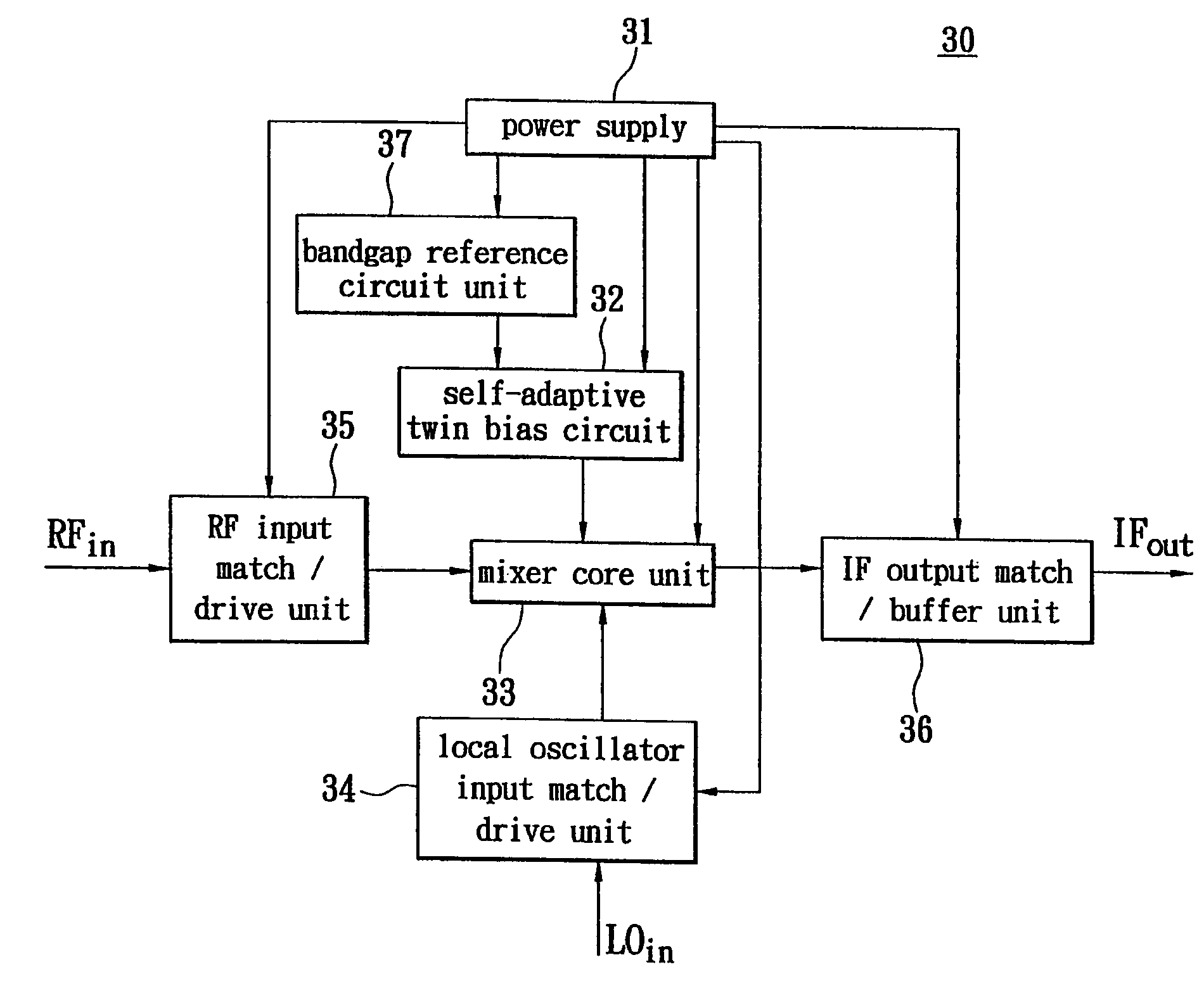
An active mixer with self-adaptive bias feedback is described and resolves a poor linearity, inconvenient design of a bias circuit, and other defects of a conventional mixer. The dual self-feedback bias structure according to this invention is used. The active mixer with self-adaptive bias feedback has a power supply, an RF input match / drive unit, a local oscillator input match / drive unit, a mixer core unit, a self-adaptive twin bias circuit and an IF output match / buffer unit. This invention improves the linearity of a conventional mixer and does not affect other characteristics. There are fewer components in this invention; an area of the mixer is thus smaller. Further, this invention may improve temperature response, increase yield factor, and lower unit cost. The dual self-feedback bias structure is designed for further application to other semiconductor manufacturing processes, components, and microwave products.

Description

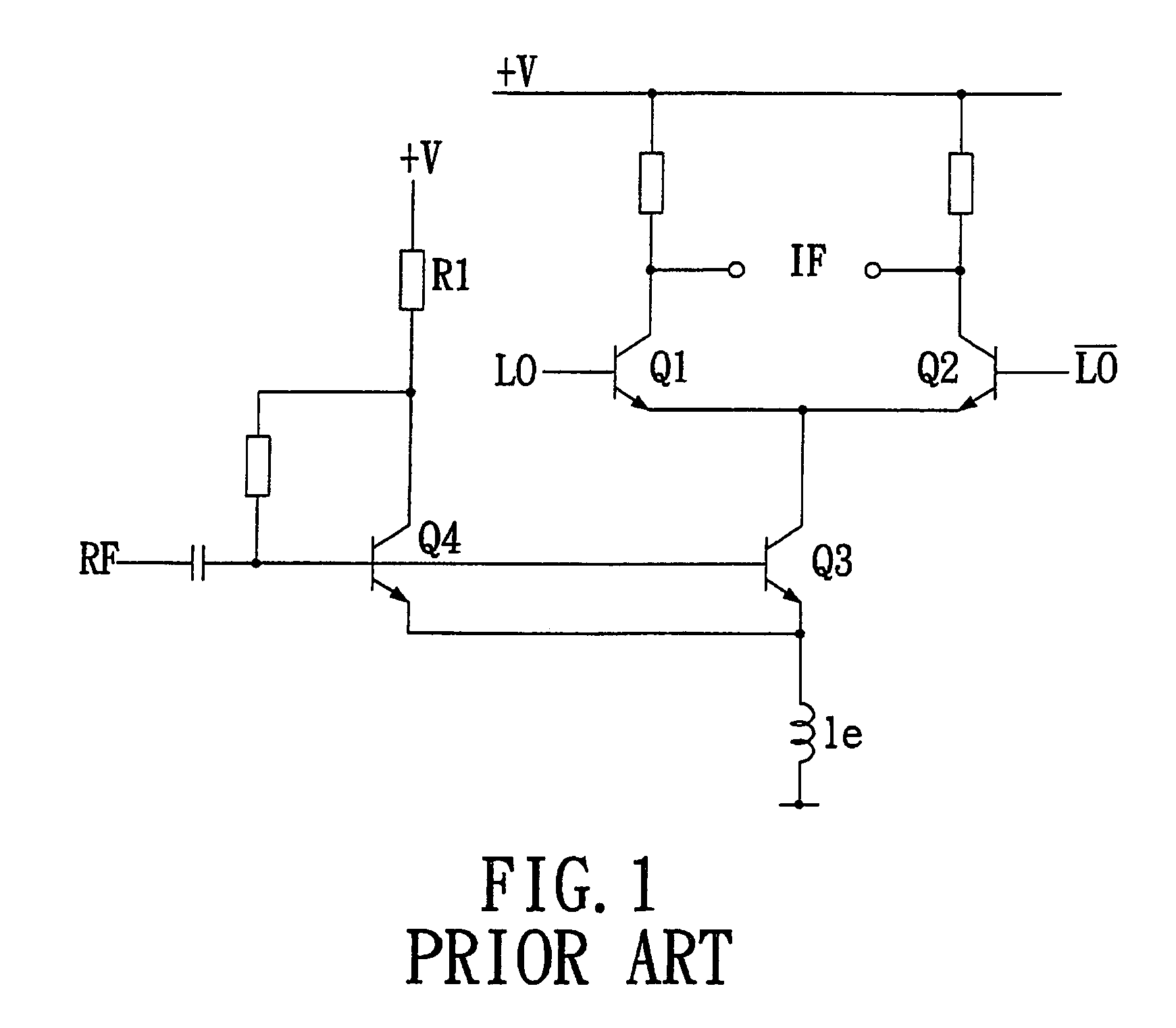
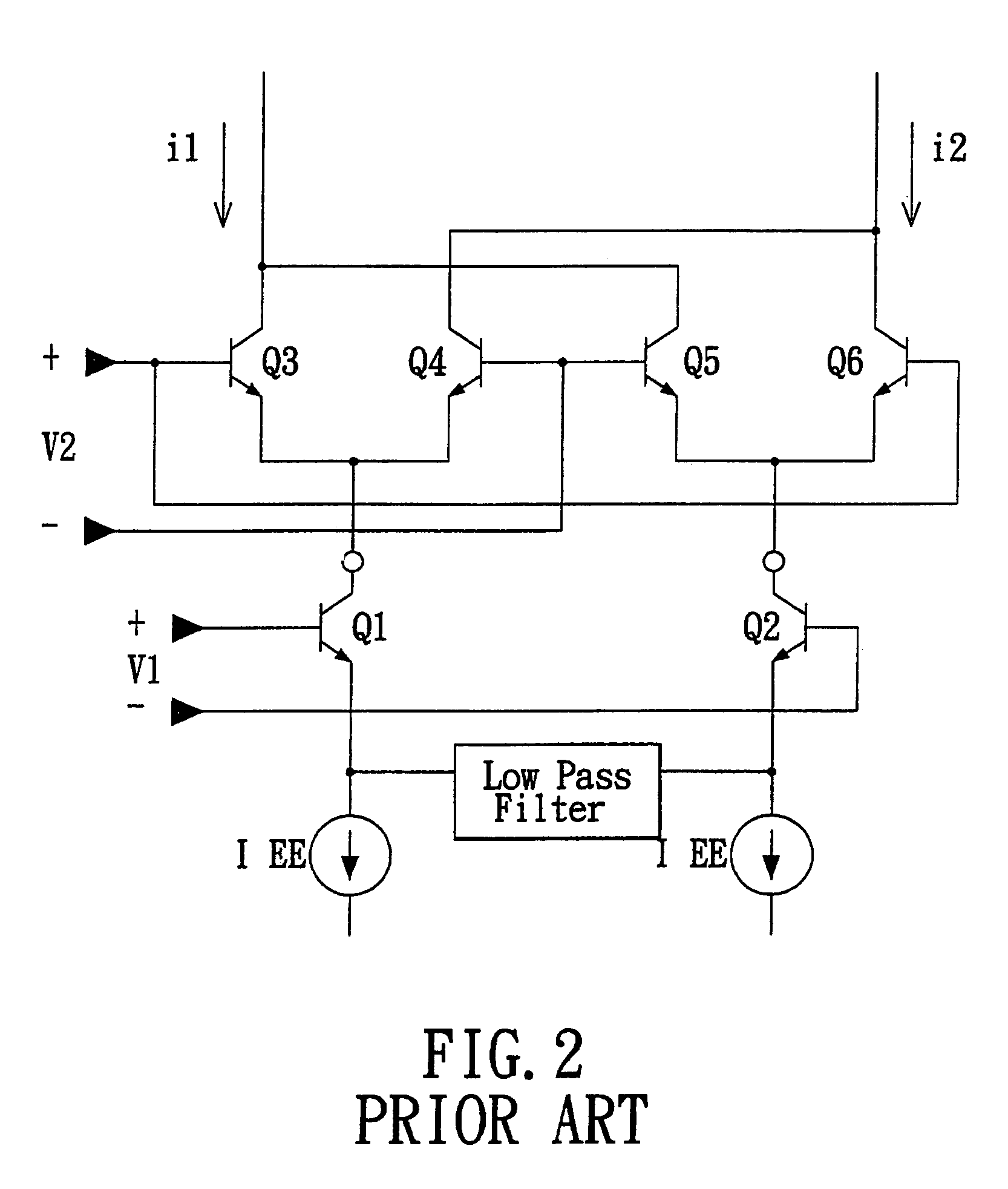
BACKGROUND OF THE INVENTION[0001]1. Field of the Invention[0002]This invention provides an active mixer with self-adaptive bias feedback and particularly to a design and concept of a dual self-feedback bias structure.[0003]2. Description of Related Art[0004]In various communication systems, a mixer is an essential element. The quality and performance of communication system depends greatly on the mixer's linearity, conversion gain, signal-to-noise rate, and temperature response as characteristics. Generally speaking, a bias may be provided in the mixer, and when an input signal is increased in a conventional bias circuit, the linearity of the mixer becomes quite poor. Thus, it is improved to be a single feedback bias circuit for slight increase of the linearity of mixer, but the increased linearity cannot yet meet requirements.[0005]Recently, many methods for improving the linearity of mixer have been disclosed, as described in U.S. Pat. No. 6,205,325 (FIG. 1), U.S. Pat. No. 6,472,9...

Claims


Application Information

Patent Timeline
Patent Type & Authority Patents(United States)
IPC IPC(8): H04B1/04
CPCH03D7/1425H03D7/1433H03D7/1408H03D7/145H03D7/1458H03D7/1491H03D2200/0043
Inventor WU, CHING-KUOCHEN, CHIH-WEICHANG, YUN-SHANWONG, SHYH-CHYI
Owner RICHWAVE TECH CORP
Learn More