Multimode optical transmission apparatus and multimode optical transmission system

a transmission apparatus and optical transmission technology, applied in the direction of optical radiation measurement, instruments, photometry using electric radiation detectors, etc., can solve the problems of optical fiber, noise called a modal noise, and deterioration of transmission characteristics

Inactive Publication Date: 2008-10-21
PANASONIC CORP
View PDF2 Cites 0 Cited by
  • Summary
  • Abstract
  • Description
  • Claims
  • Application Information

AI Technical Summary

Benefits of technology

[0010]Therefore, an object of the present invention is to provide a multimode optical transmission apparatus and a multimode optical transmission system capable of reducing, even if an interference between modes exerts a significant influence, a deterioration of a noise characteristic and a distortion characteristic caused by the interference between the modes.
[0026]As described above, according to the present invention, the frequency of the high frequency modulated signal with which the optical signal is modulated is set to an appropriate value based on the group delay information of each mode which propagates in the multimode optical transmission line, thereby reducing the deterioration of the noise characteristic and the distortion characteristic caused by the interference between the modes. Thus, even when a multimode optical fiber is used as the optical transmission line, the deterioration of an optical transmission quality can be prevented, and the optical transmission system of a high quality can be provided at a low cost.
[0027]Further, the frequency of the superimposed signal with which the optical signal is modulated is set to an appropriate value based on the group delay information of each mode which propagates in the multimode optical transmission line, thereby reducing the deterioration of the noise characteristic and the distortion characteristic caused by the interference between the modes. Moreover, the high frequency modulated signal is frequency-multiplexed with the superimposed signal, thereby widening the line width of the light source. Therefore, the deterioration of the noise characteristic and the distortion characteristic caused by the interference between the modes can be increasingly reduced.
[0028]By providing the mode group delay information estimation section, the group delay information of each mode which propagates in the multi mode optical transmission line can be estimated. Thus, even when a network configuration is changed, the deterioration of the noise characteristic and the distortion characteristic caused by the interference between the modes can be reduced. Moreover, the mode group delay information estimation section can accurately estimate, by using the short pulse signal, the group delay information of each mode which propagates in the multimode optical transmission line.

Problems solved by technology

However, the optical transmission system using the multimode optical fiber has a plurality of propagation modes in its optical transmission line, so that a transmission characteristic is deteriorated.
That is, in the optical transmission system using the multimode optical fiber, some of the propagation modes interfere with each other, which causes a noise called a modal noise.
Further, a bending of the optical fiber or a gap between connectors substantially deteriorates the transmission characteristic.
As described above, when the optical transmission is performed using the multimode optical fiber, the transmission characteristic is deteriorated due to the interference between the modes.
Particularly, when the optical transmission line has a small number of modes, or when a light source has a narrow line width, the possibility for the interference between the modes is increased, thereby significantly deteriorating the transmission characteristic.
For example, when a surface emitting laser and a 1.3 μm band single mode optical fiber are used as the light source and the optical transmission line, respectively, the interference between the modes is increased, thereby significantly deteriorating the transmission characteristic.
In this case, the optical transmission line has a small number of modes and the light source has a narrow line width, so that the interference between the modes significantly deteriorates the noise characteristic and the distortion characteristic of the multimode optical transmission line.

Method used


Image

  • Multimode optical transmission apparatus and multimode optical transmission system
  • Multimode optical transmission apparatus and multimode optical transmission system
  • Multimode optical transmission apparatus and multimode optical transmission system

Examples


first embodiment

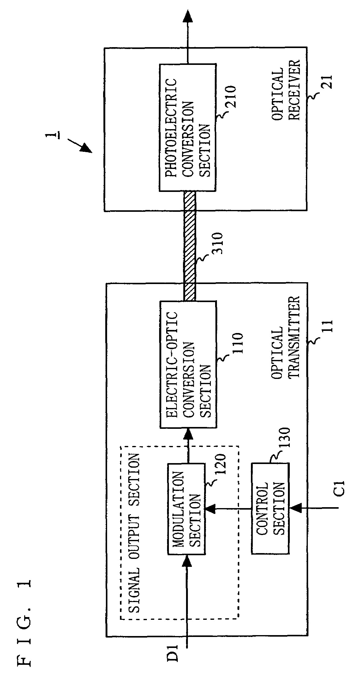
[0041]FIG. 1 is a block diagram illustrating an exemplary structure of a multimode optical transmission system 1 according to a first embodiment of the present invention. As shown in FIG. 1, the multimode optical transmission system 1 comprises an optical transmitter 11 and an optical receiver 21, which are connected to each other via a multimode optical transmission line 310. The optical transmitter 11 includes an electric-optic conversion section 110, a modulation section 120, and a control section 130. The optical receiver 21 includes a photoelectric conversion section 210.

[0042]As shown in FIG. 1, data D1 is inputted to the optical transmitter 11 as data to be transmitted. The modulation section 120 modulates the data D1 and outputs the modulated data as a high frequency modulated signal. The electric-optic conversion section 110 coverts, into an optical signal, the high frequency modulated signal outputted by the modulation section 120, and outputs the optical signal to the mul...

second embodiment

[0061]In the first embodiment, the method for determining the frequency of the high frequency modulated signal based on the group delay difference Δτ between the reference mode and the first-order mode is described. In a second embodiment, when a superimposed signal is frequency-multiplexed with the high frequency modulated signal, the frequency of the superimposed signal is set to an optimal value so as to reduce the deterioration of the noise characteristic and the distortion characteristic caused by the interference between the modes.

[0062]FIG. 5 is a block diagram illustrating an exemplary structure of a multimode optical transmission system 2 according to the second embodiment of the present invention. As shown in FIG. 5, the multimode optical transmission system 2 comprises an optical transmitter 12 and an optical receiver 22, which are connected to each other via a multimode optical transmission line 310. The optical transmitter 12 includes an electric-optic conversion sectio...

third embodiment

[0079]In order to reduce the deterioration of the noise characteristic and the distortion characteristic caused by the interference between the modes, a method for appropriately setting the frequency of the high frequency modulated signal is used in the first embodiment and a method for appropriately setting the frequency of the superimposed signal which is frequency-multiplexed with the high frequency modulated signal is used in the second embodiment. In a third embodiment, described is a method for calculating the group delay difference Δτ between the reference mode and the first-order mode each propagating in the multimode optical transmission line 310 by utilizing the fact that the change in frequency of the high frequency modulated signal or change in frequency of superimposed signal changes an amount of distortion or an amount of noise.

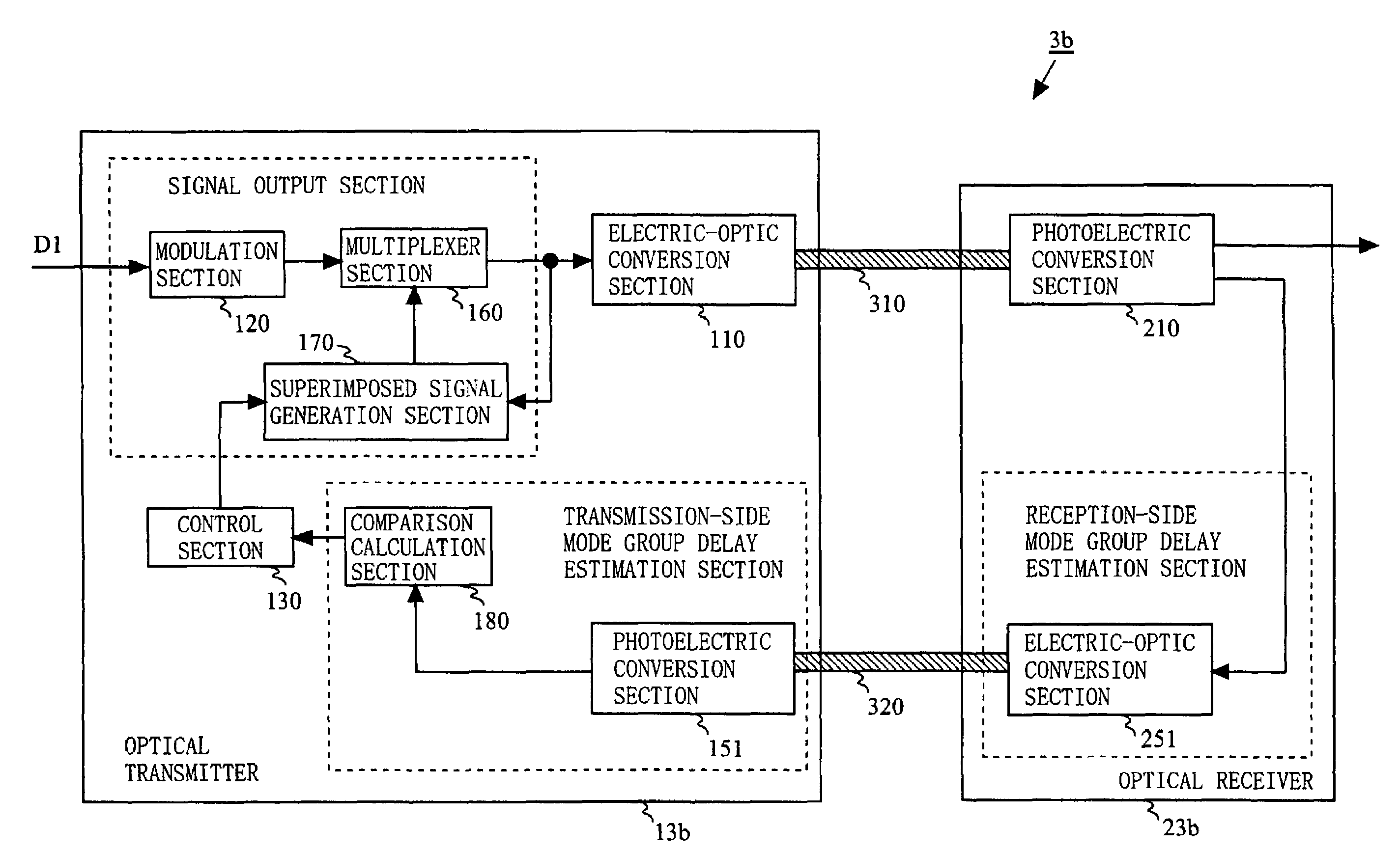
[0080]FIG. 7A is a block diagram illustrating an exemplary structure of a multimode optical transmission system 3a according to the third embod...


PUM


Abstract

A multimode optical transmission system reduces a deterioration of a noise characteristic and a distortion characteristic caused by an interference between modes. In an optical transmitter, a signal output section outputs a predetermined signal based on an inputted electrical signal. A control section controls the signal output section so as to adjust a frequency component of the signal outputted by the signal output section based on group delay information of modes which propagate in a multimode optical transmission line. An electric-optic conversion section converts, into an optical signal, the signal outputted by the signal output section, and transmits the optical signal via the multimode optical transmission line.

Description

BACKGROUND OF THE INVENTION[0001]1. Field of the Invention[0002]The present invention relates to a multimode optical transmission apparatus and a multimode optical transmission system for transmitting an optical signal via a multimode optical transmission line, and more particularly relates to a multimode optical transmission apparatus and a multimode optical transmission system for reducing a deterioration of a noise characteristic and a distortion characteristic caused by an interference between modes.[0003]2. Description of the Related Art[0004]For example, in D. R. Hjelme, and A. R. Mickelson, “Microbending and modal noise”, Applied Optics, Vol. 22, No. 23, Dec. 1, 1983, pp. 3874-3879 (hereinafter, referred to as “Non-patent Document 1”), an optical transmission system using a conventional multimode optical fiber is disclosed. FIG. 9 is a block diagram illustrating an exemplary structure of the conventional optical transmission system disclosed in Non-patent Document 1. As shown...

Claims


Application Information

Patent Timeline
Patent Type & Authority Patents(United States)
IPC IPC(8): G01J1/44G01J4/00
CPCH04B10/2581
Inventor NIIHO, TSUTOMUMASUDA, KOUICHI
Owner PANASONIC CORP
Why Eureka
Try Eureka