Light emitting device with specific four color arrangement

a light emitting device and color arrangement technology, applied in the field of light emitting devices, can solve the problems of deteriorating image quality, reducing the color reproduction of the light emitting device, increasing the electric power consumption of the display device, etc., and achieves low luminous efficiency, high luminous efficiency, and low luminous efficiency.

Inactive Publication Date: 2008-10-21
SEMICON ENERGY LAB CO LTD
View PDF42 Cites 24 Cited by
  • Summary
  • Abstract
  • Description
  • Claims
  • Application Information

AI Technical Summary

Benefits of technology

[0011]It is an object of the invention to provide a light emitting device in which burden on a light emitting element having low luminous efficiency is relieved, and the deterioration of a light emitting element, the deterioration of color reproduction due to the deteriorated light emitting element, and increase in electric power consumption can be suppressed.
[0016]A light emitting element which emits a neutral color plays an auxiliary role with respect to a light emitting element having low luminous efficiency, when, a neutral color is indicated by combining light emission of a light emitting element having higher luminous efficiency and light emission of the light emitting element having low luminous efficiency. Accordingly, in a light emitting element having low luminous efficiency, a burden on light emission is relieved since brightness required for display can be reduced compared with the case of displaying a neutral color by combining the three primary colors. Thus, the life of a light emitting element having low luminous efficiency can be particularly extended. As a result, the deterioration of a light emitting element or the reduction image quality caused by the deteriorated light emitting element can be suppressed. Further, more colors can be indicated by providing a light emitting element which emits a neutral color, therefore, the range of color reproduction range of a light emitting device is widened.
[0017]The invention relieves the burden on a light emitting element having low luminous efficiency or a light emitting element of a luminescent color to which the human eye has lower sensitivity. Accordingly, deterioration of the light emitting element or the reduction in image quality due to the deteriorated light emitting element can be suppressed. Moreover, the light emitting device which can indicate more colors resulting in expanding color reproduction range can be obtained.

Problems solved by technology

Flowing a lot of current to a light emitting element to increase brightness of the light emitting element make the light emitting element promotes the deterioration of the light emitting element, and leads to increase in electric power consumption of a display device.
What is more, when emission wavelength shifts due to a deteriorated light emitting element, color reproduction of a light emitting device decreases and thus sometimes image quality is deteriorated.

Method used


Image

  • Light emitting device with specific four color arrangement
  • Light emitting device with specific four color arrangement
  • Light emitting device with specific four color arrangement

Examples


embodiment 1

[0046]In this embodiment, a fight emitting device according to the present invention is describe However, the light emitting device according to the invention is not limited to the one shown in this embodiment.

[0047]FIG. 3 is a frame format showing a top view of a fight emitting device to which the invention is applied. In FIG. 3, reference numeral 6510 shown by a dotted line denotes a drive circuit portion (a source side drive circuit); 6511, a pixel portion; and 6512, a drive circuit portion (a gate side drive circuit). The light emitting element of the invention is provided for the pixel portion 6511. The driver circuit portions 6510 and 6512 are connected to each other through an FPC 6503 which is an external input terminal and one group of wirings formed over a substrate 6500. Signals are inputted into the drive circuit portions 6510 and 6512 by receiving a video signal, a clock signal, a start signal, a reset signal or the like from the FPC (flexible printed circuit) 6503. A p...

embodiment 2

[0063]In this embodiment, a light emitting device in which arrangement of light emitting elements in one pixel is different from the one shown in FIG. 1 is described

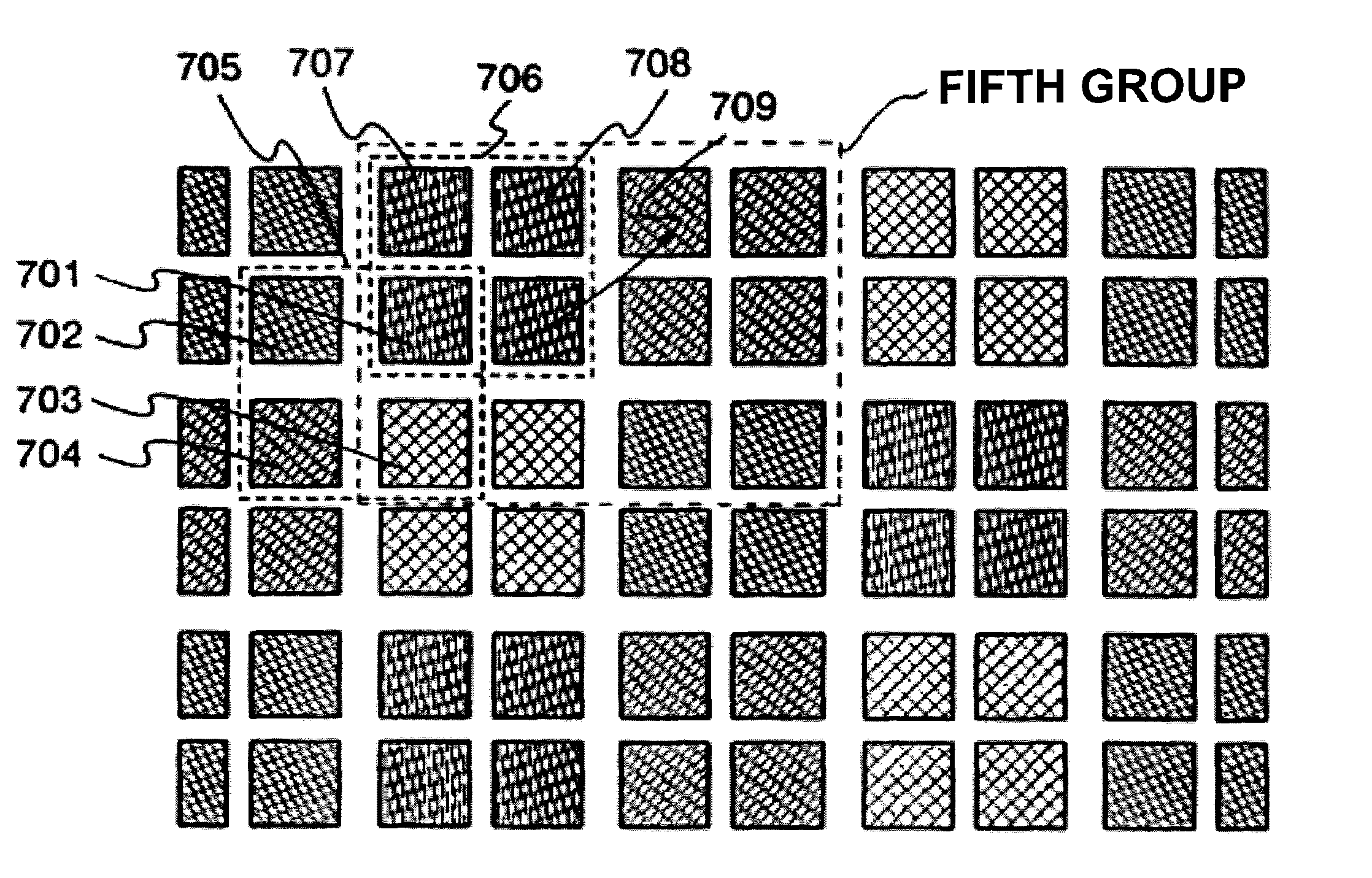
[0064]A light emitting device in this embodiment has a first light emitting element 701 which emits red light, a second light emitting element 702 which emits green light, a third light emitting element 703 which emits blue light, and a fourth light emitting element 704 which emits blue-tinged green light as shown in FIG. 7.

[0065]In the light emitting device in this embodiment, each of from the first light emitting element 701 to the fourth light emitting element 704 has four light emitting elements which are arranged in two rows and in two columns. A pixel 705 includes four light emitting elements, namely the first light emitting element 701 to the fourth light emitting element 704. A plurality of the pixels 705 are arranged.

[0066]In the light emitting device in this embodiment, as the first light emitting element 701, ...

embodiment 3

[0073]In this embodiment, a cross-sectional structure of a light emitting device to which the present invention is applied is explained. However, the structure of the light emitting device according to the invention and a substance constituting the light emitting device and the like are not limited to those shown in this embodiment.

[0074]In FIGS. 8A to 8C, a transistor 11 surrounded by a dotted line is provided for driving a light emitting element 12. The light emitting element 12 corresponds to any one of the first light emitting element 301a to the fourth light emitting element 301d shown in Embodiment 1, and the transistor 11 corresponds to any one of driving transistors 321a to 321d shown in Embodiment 1. The light emitting element 12 includes a first electrode 13, a second electrode 14, and a light emitting layer 15 sandwiched by these electrodes. A drain of the transistor 11 and the first electrode 13 are electrically connected to each other by a wiring 17 which passes through...


PUM


Abstract

It is an object of the invention to provide a light emitting device in which burden on a light emitting element having low luminous efficiency is relieved, and the deterioration of a light emitting element, the reduction in color reproduction due to the deteriorated light emitting element, and increase in electric power consumption can be suppressed. A light emitting device according to the invention has light emitting elements each of which emits one of colors corresponding to three primary colors. Further, one feature of the light emitting device according to the invention has a light emitting element which emits a neutral color. The light emitting device according to the invention has a structure in which a plurality of pixels having light emitting elements each of which emits one of colors corresponding to three primary colors, and a light emitting element which emits a neutral color as one group, are arranged.

Description

BACKGROUND OF THE INVENTION[0001]1. Field of the Invention[0002]The present invention relates to a light emitting device, in particular, to a light emitting device which can display an image which includes multicolors by combining light emission having different colors.[0003]2. Description of the Related Art[0004]A light emitting device utilizing light emitted from an electroluminescence element (a light emitting element) is a device which highly draws attention as a display device having wide view angles and low power consumption.[0005]In recent years, in a field of developing a light emitting device, the research and development of a light emitting device capable of displaying a high quality full color image has been accelerated to ensure the market of display devices and the like for various information processing devices such as a television receiver or a car navigation system.[0006]In order to display a full color image, it is required that regions emitting light emission of th...

Claims


Application Information

Patent Timeline
Patent Type & Authority Patents(United States)
IPC IPC(8): H01L51/00G09G5/02G09G3/30H01J1/62H05B33/12H05B44/00
CPCH05B33/0821H05B33/0857H01L33/62H01L27/156H05B33/145H05B45/40H05B45/20
Inventor OHTANI, HISASHI
Owner SEMICON ENERGY LAB CO LTD
Why Eureka
Try Eureka