System and technique for retrieving depth information about a surface by projecting a composite image of modulated light patterns

a composite image and surface technology, applied in the field of structured light systems, can solve the problems of cumbersome process, cumbersome process, and known structured light illumination techniques used for automated inspection and measuring surface topologies, and achieve the effect of more detailed and/or larger depth mappings

Inactive Publication Date: 2008-10-21
UNIV OF KENTUCKY RES FOUND
View PDF10 Cites 182 Cited by
  • Summary
  • Abstract
  • Description
  • Claims
  • Application Information

AI Technical Summary

Benefits of technology

[0027]Further unique to the invention is an opportunity to, after capturing the first reflected image, project a second composite image comprising a second plurality of modulated structured light patterns, at the object so that second pattern information from a second reflected image can be recovered for each of the second plurality of modulated structured light patterns. This feature of time-sequencing composites, an example of which is depicted by the isometrics in FIGS. 9A-9B, offers the capability to produce a depth map of the surface(s) of the object using pattern information recovered from two, or more, projected composite images. Such a depth map can reconstruct several surfaces of the object from reflected imaged information received sequentially in time.
[0028]In another aspect of the invention a second composite image comprising a second plurality of modulated structured light patterns can be projected, at the object. Here, preferably, the first and second composite images are projected using, respectively, electromagnetic energy radiated within a first and a second wavelength range, whereby the first and second wavelength ranges have no overlap making the composites ‘bandwidth limited’. An example of this alternative is depicted by the isometric drawing in FIG. 7. Such a technique provides for a means by which, whether done simultaneously or sequentially, two or more composite images can be projected at the object to gather additional surface information—providing the capability to recover additional depth information and, thus, produce more detailed and / or larger depth mappings.

Problems solved by technology

Either way, maximum resolution is limited by the maximum spatial frequency used.
This is quite a cumbersome process.
As mentioned, known structured-light illumination techniques used for automated inspection and measuring surface topologies, are cumbersome.
Traditional 3D acquisition devices use a single scanning laser stripe scanned progressively over the surface of the target object, placing a burden on the object to remain static and a burden on data acquisition to capture all the stripe images.
These known multi-stripe patterns suffer from drawbacks such as introducing ambiguities in the surface reconstruction around surface discontinuities, overly sensitive to surface reflectance variations (i.e., albedo), and / or they suffer from lower lateral resolution caused by the required spacing between stripes.
These known systems are simply not suitable for real-time imaging.

Method used


Image

  • System and technique for retrieving depth information about a surface by projecting a composite image of modulated light patterns
  • System and technique for retrieving depth information about a surface by projecting a composite image of modulated light patterns
  • System and technique for retrieving depth information about a surface by projecting a composite image of modulated light patterns

Examples


example 1a

Derivation & Analysis Discussion-Composite Patterning Employing PMP

[0049]The PMP range finding method has several advantages, it is a pixel-wise calculation, resistant to ambient light, resistant to reflection variation and it can have as few as three frames for whole-field depth reconstruction. Sinusoid patterns are projected and shifted by a factor of 2;T / N for N times as

Inp(xp,yp)=Ap+Bp cos(2πfφyp−2πn / N)  Eqn. (1)

where Ap and Bp are the projection constants and (xp, yp) is the projector coordinates. The yp dimension is in the direction of the depth distortion and is called the phase dimension. On the other hand, xp dimension is perpendicular to the phase dimension, so it has been coined herein, the orthogonal dimension. Thus, frequency f100 of the sinusoid wave is in the phase direction / dimension. The subscript n represents the phase shift index and n=1, 2, . . . , N. where N is the total number of phase shifts.

[0050]The reflected intensity images from the object surface after su...

example 1b

Addendum Summary to Discussion and Analysis Employing PMP

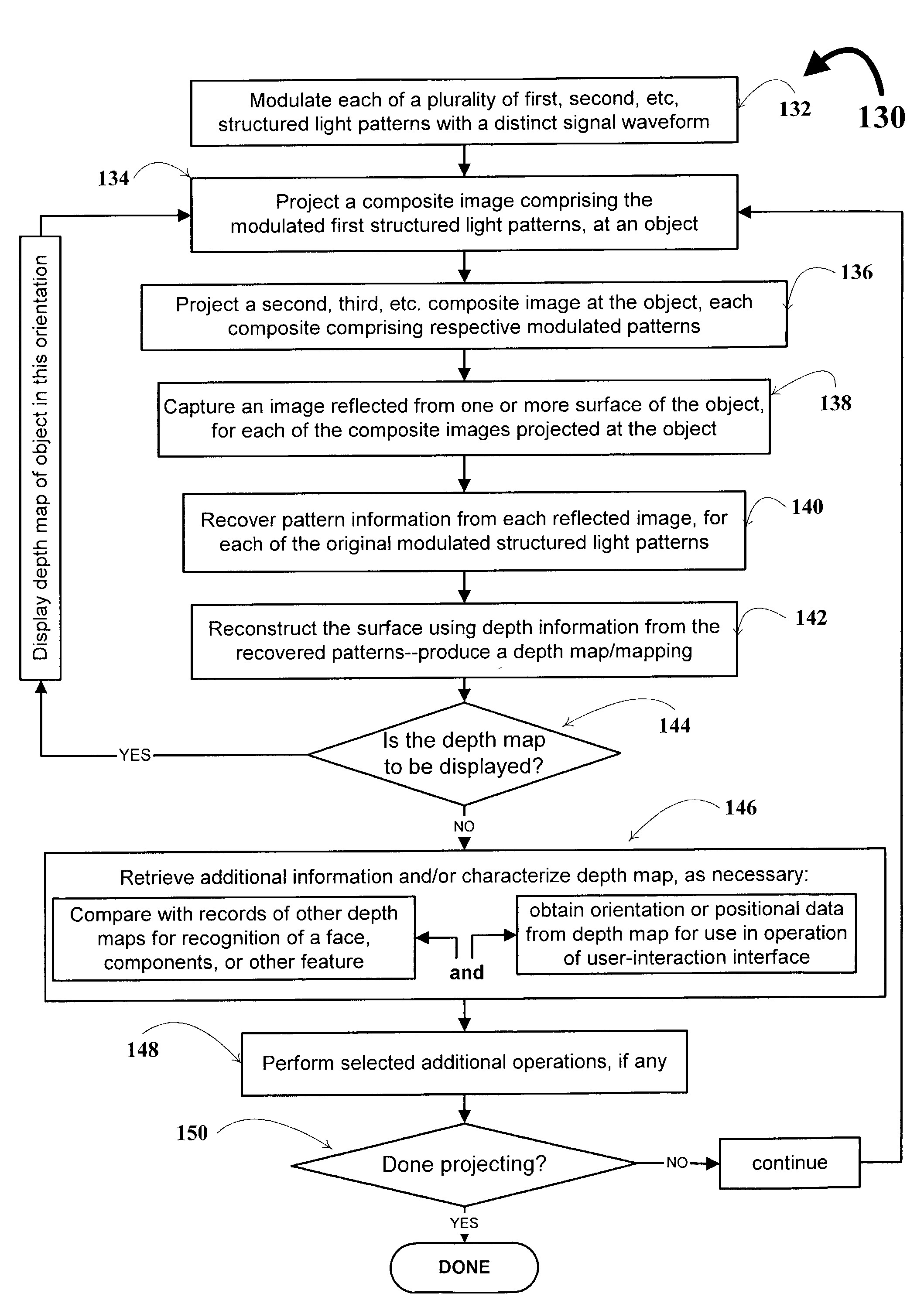
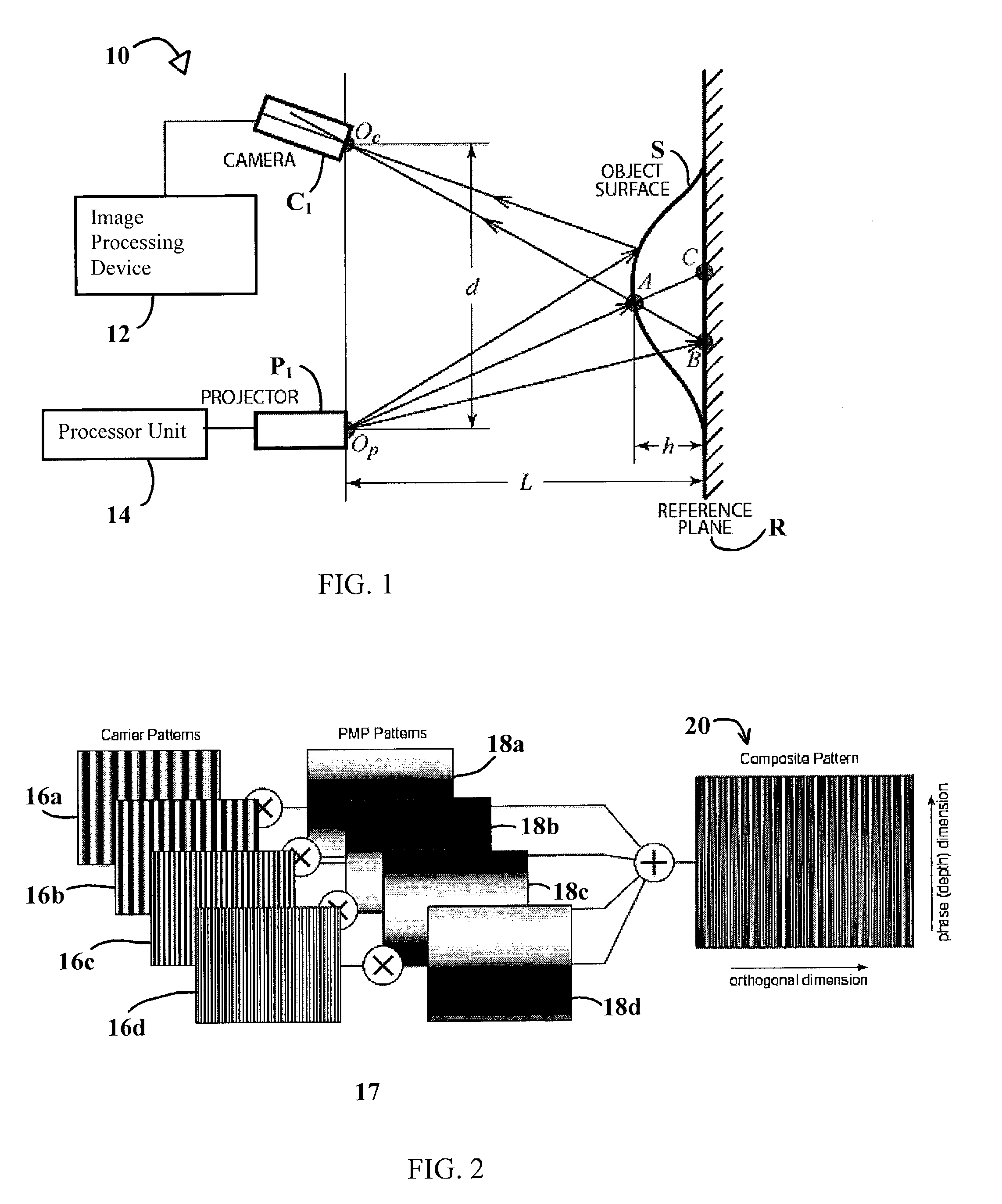
[0066]As mentioned, one core feature of the technique of the invention is the projection of a composite 20, FIG. 2 of modulated patterns. Assuming scale and offset of the composite function has a transmittance between 0 and 1, the composite image may be represented by the following expression:

[0067]Scp⁡(x,y)=∑n=1N⁢fn⁡(x)⁢φn⁡(y)Expression⁢[I]

The structured light pattern set is represented with a 1-D function fn(x) where x is along the phase dimension. The modulating function is φn(y) where y is along the orthogonal dimension. The index is n=1, 2, . . . N. Drawing from communications concepts to use AM frequency division multiplexing, encode the N patterns. Let

φn(y)=A(1+cos(2πfy,ny))  Expression [II]

where A is a scaling constant and fy,n is the orthogonal frequency.

[0068]The well known multi-pattern PMP technique employed here to provide the structured light patterns for use in the composite pattern, uses phase shifted sinusoids...

example 1c

Summary of Application of Techniques Discussed in Examples 1A-1B

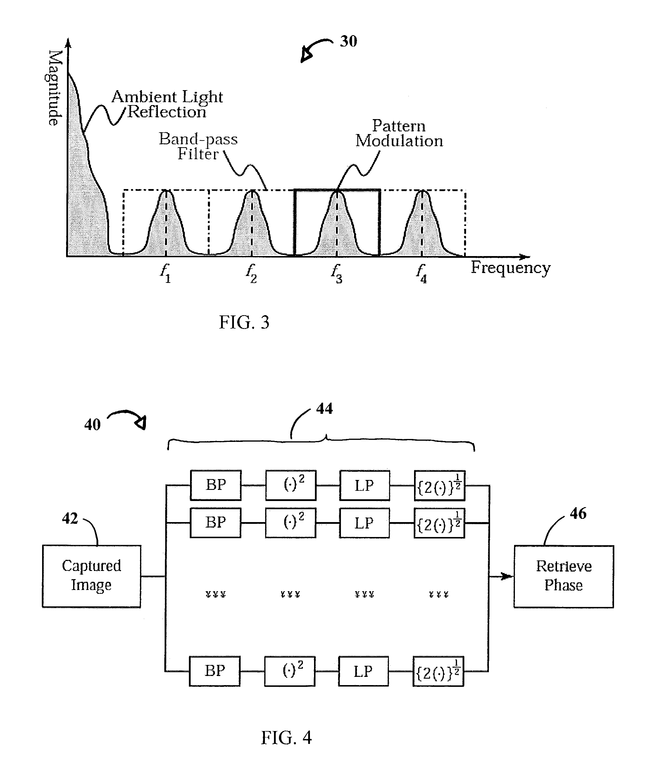
[0084]Referencing the various FIGs throughout this EXAMPLE 1C, the following is provided merely for purposes of further understanding the novel features of the invention. A Texas Instruments (TI) Digital Light Processor (DLP) projector, P1, was used with an 800×600 micro-mechanical mirror array. The framegrabber 12, a DT3120, grabs the image from the CCD monochrome camera with spatial resolution of 640×480 with 8 bits intensity resolution. To simplify decoding, the frequency across the phase direction A, is selected to be unit, or 1, frequency: No unwrapping algorithm need be implemented. In this experiment, number of patterns, N=4; carrier frequencies of the projector fnp were 50, 85, 120 and 155 cycles per field of view for an orthogonal field of view width of 800 pixels. The corresponding received carrier frequencies were 33, 56, 79, and 103 cycles per field of view with a field of view of 640 pixels. The lowest modu...


PUM


Abstract

A technique, associated system and program code, for retrieving depth information about at least one surface of an object. Core features include: projecting a composite image comprising a plurality of modulated structured light patterns, at the object; capturing an image reflected from the surface; and recovering pattern information from the reflected image, for each of the modulated structured light patterns. Pattern information is preferably recovered for each modulated structured light pattern used to create the composite, by performing a demodulation of the reflected image. Reconstruction of the surface can be accomplished by using depth information from the recovered patterns to produce a depth map/mapping thereof. Each signal waveform used for the modulation of a respective structured light pattern, is distinct from each of the other signal waveforms used for the modulation of other structured light patterns of a composite image; these signal waveforms may be selected from suitable types in any combination of distinct signal waveforms, provided the waveforms used are uncorrelated with respect to each other. The depth map/mapping to be utilized in a host of applications, for example: displaying a 3-D view of the object; virtual reality user-interaction interface with a computerized device; face—or other animal feature or inanimate object—recognition and comparison techniques for security or identification purposes; and 3-D video teleconferencing/telecollaboration.

Description

[0001]This application claims priority to pending U.S. provisional patent application No. 60 / 382,202 filed 21 May 2002 on behalf of the assignee hereof.[0002]The invention disclosed herein was made with United States government support awarded, in part, by the NASA EPSCoR Cooperative agreement NCC5-222 and proposal number N02R04 D through Western Kentucky University, and in part by support awarded by National Science Foundation under grant EPS-9874764. Accordingly, the U.S. Government has certain rights in this invention.BACKGROUND OF THE INVENTION[0003]1. Field of the Invention[0004]In general, the present invention relates to structured light systems that utilize multi-pattern techniques, whereby multiple projected structured light patterns are used to reconstruct an image. More-particularly, the instant invention is directed to a technique and system that employs at least one camera and one projector used in concert for retrieving depth information about at least one surface of a...

Claims


Application Information

Patent Timeline
Patent Type & Authority Patents(United States)
IPC IPC(8): G06K9/00G06V10/145
CPCG01B11/2513G06K9/2036G06K2209/40G06V10/145G06V2201/12
Inventor HASSEBROOK, LAURENCE G.LAU, DANIEL L.GUAN, CHUN
Owner UNIV OF KENTUCKY RES FOUND
Why Eureka
Try Eureka