
Mechanism for interconnecting independent functionalities of an engine controller

a technology of engine controller and functionality, applied in the field of engine controller, can solve the problems of complex regulation of motor vehicles, and achieve the effect of facilitating the reuse of different standard components and easy configuration of engine control systems

Active Publication Date: 2008-10-21
VITESCO TECH GERMANY GMBH
View PDF8 Cites 0 Cited by
  • Summary
  • Abstract
  • Description
  • Claims
  • Application Information

AI Technical Summary

Benefits of technology

The invention provides an engine controller and method that allows for easy configuration and reuse of different standard components in different engines or control devices. The controller has multiple components that execute functions and communicate with each other through trigger signals. The trigger signals are generated by a plurality of wrappers, which are assigned to each component and can transform the signals to different types. The wrappers are programmed once during system startup and can be easily updated for changes in the connections between components. This reduces the time required for new connections and updates. The invention also allows for the reuse of standard components and the triggering of different components with the same trigger signals. Overall, the invention simplifies the process of configuring and adapting engine controllers.

Problems solved by technology

Regulators in motor vehicles are very complex as a result of their numerous input and output variables, so that modern regulating systems based on microcontrollers are used to realize these tasks.

Method used


Image

  • Mechanism for interconnecting independent functionalities of an engine controller
  • Mechanism for interconnecting independent functionalities of an engine controller
  • Mechanism for interconnecting independent functionalities of an engine controller

Examples


Embodiment Construction

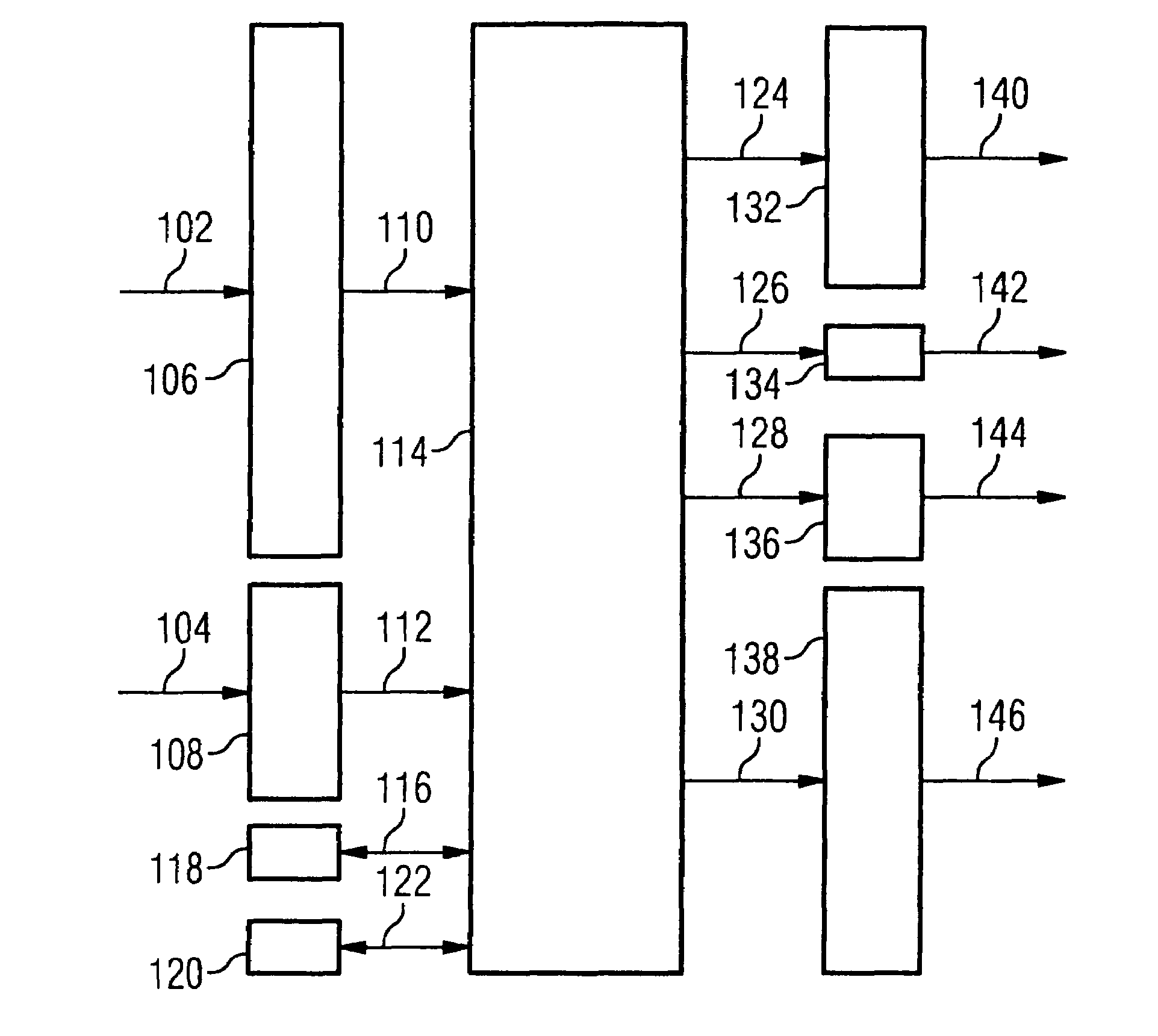
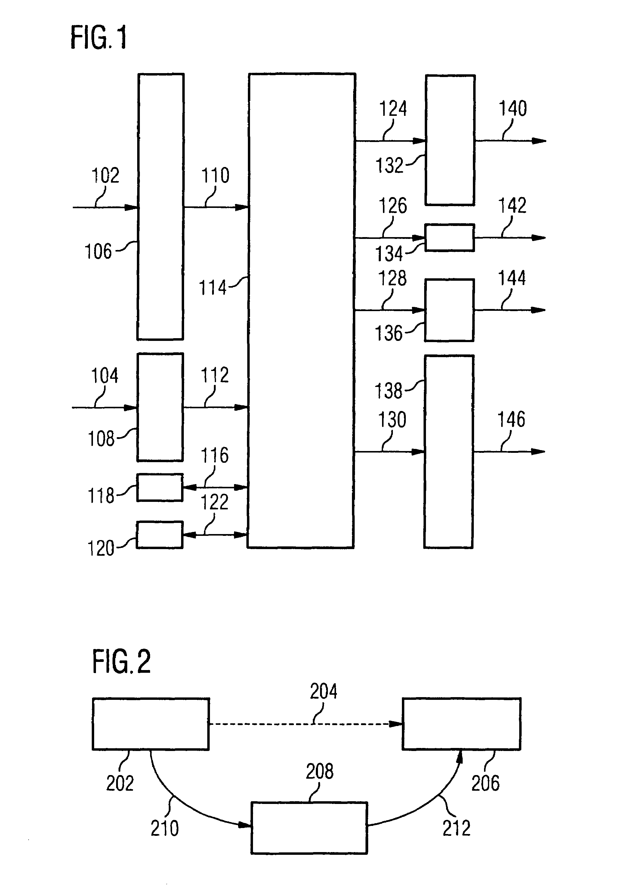
[0053]FIG. 1 shows the basic diagram of an engine controller. With the engine controller shown, the signal flow is carried out by the different sensors and set point devices 102 (e.g. accelerator adjustment, throttle position, air mass, battery voltage, intake air temperature, engine temperature, knocking intensity, lambda probes) and 104 (e.g. crankshaft speed, camshaft position, gear speed, speed) via the input / output ports 106 and 108 and further from the ports to the microcontroller 114 and its components by way of the connections 110 and 112.

[0054]The data is transferred between the microcontroller 114 and the CAN bus 118 by way of the connection 116. The CAN bus 118 ensures that all devices are networked with one another via a single cable. The data is transferred between the microcontroller 114 and a diagnosis system 120 by way of the connection 122.

[0055]The microcontroller 114 with its components realizes its function on the basis of a program which is permanently stored in...


PUM


Abstract

Electronic engine controllers contain a multitude of individual components that, in part, trigger one another. Until now, a change made to these trigger connections required a change, for example, in the source code of the engine controller. According to the invention, all trigger connections are realized by interconnecting wrappers, which receive the trigger signal from a component and—optionally after translating the trigger signal into a trigger signal of a differing type route this trigger signal to the second component to be triggered. In order to produce or change a trigger connection, it is only required to change the configuration of the wrappers.

Description

BACKGROUND OF THE INVENTION[0001]1. Field of the Invention[0002]The invention relates to an engine controller for controlling processes of the drivetrain (engine and / or drives) in motor vehicles having combustion engines (gasoline or diesel engines). The term engine controller here denotes both an engine control device and also a complex of functionalities, which are required to control an engine.[0003]2. Prior Art[0004]One of the decisive fields of application of microelectronics in modern motor vehicles is among others the control of the drivetrain. The regulation of the idling speed, the lambda control and the regulation of the electronic ignition system play a paramount role here. An active engine regulator and an adaptive drive controller are essential means for adjusting the systems to the respective driving situation.[0005]Regulators in motor vehicles are very complex as a result of their numerous input and output variables, so that modern regulating systems based on microcon...

Claims


Application Information

Patent Timeline
Patent Type & Authority Patents(United States)
IPC IPC(8): G06F19/00
CPCF02D41/266F02D29/02F02D45/00G05B19/042
Inventor KULZER, JOSEFTSCHOCHNER, HARALDVEIT, FREDDY
Owner VITESCO TECH GERMANY GMBH
Learn More