
Alumina layer with controlled texture

a technology of alumina layer and controlled texture, which is applied in the field of coating cutting tool inserts, can solve the problems of coating flaking, -al/sub>2/sub>o/sub>3 phase is more difficult to be nucleated and grown at reasonable cvd temperatures, and none of these systems have been commercially successful, so as to improve cutting properties, reduce dislocation density, and increase toughness

Inactive Publication Date: 2008-10-28
SECO TOOLS AB
View PDF25 Cites 28 Cited by
  • Summary
  • Abstract
  • Description
  • Claims
  • Application Information

AI Technical Summary

Benefits of technology

The present invention provides a new and improved alumina layer with strong, fully controlled texture. The alumina layer is composed of columnar α-Al2O3 grains with texture coefficients that meet certain requirements. The texture-controlled alumina layer has improved cutting properties and is free from transformation stresses. The invention also provides a method for coating a substrate with the alumina layer. The technical effects of the invention include improved performance and toughness of cutting tools and better quality of coatings.

Problems solved by technology

During metal cutting, the κ→α phase transformation has confirmed to occur resulting in flaking of the coating.
However, the stable α-Al2O3 phase has been found to be more difficult to be nucleated and grown at reasonable CVD temperatures than the metastable κ-Al2O3.
It is worth noting that none of these systems have been commercially successful.
However, in this work it was not realised that nucleation surface controls the phase composition of Al2O3 and that deposition of α-Al2O3 is thus possible at lower deposition temperatures.

Method used


Image

  • Alumina layer with controlled texture
  • Alumina layer with controlled texture
  • Alumina layer with controlled texture

Examples


example 1

[0055]Cemented carbide cutting inserts with a composition of 5.9% Co and balance WC (hardness about 1600 HV) were coated with a layer of MTCVD Ti(C,N). The thickness of the MTCVD layer was about 2 μm. On to this layer two different layers consisting of about 10 μm α-Al2O3 were deposited:

[0056]Layer a) contained a (104) textured layer and was deposited according to the present invention at 1000° C. The detailed process data is given in Table 1.

[0057]Layer b) was deposited according to the prior art.

[0058]Layer c) contained a (104) textured layer and was deposited according to the present invention at 800° C. The detailed process data is given in Table 2.

[0059]

TABLE 1Deposition process for a Layer a) with (104) texture at 1000° C.:Step 1: Bonding layerGas mixtureTiCl4 = 2.8%AlCl3 = 0.8-4.2%CO = 5.8%CO2 = 2.2%N2 = 5-6%Balance: H2Duration60 minTemperature1000° C.Pressure100 mbarStep 2: PurgeGasAr = 100%Duration5 minTemperature1000 C.Pressure50 mbarStep 3: Pulse 1Gas mixtureTiCl4 = 1.6%A...

example 2

[0061]Layers a, b and c were studied using X-ray diffraction. The texture coefficients were determined are presented in Table 3. As clear from Table 3 the layer according to the present invention exhibits a strong (104) texture when deposited either at 1000° C. or 780° C. Typically, for this growth mode the (116) reflection is somewhat more profound than the other background reflections.

[0062]

TABLE 3HklInvention, layer aPrior art, layer b,Invention, layer c0120.240.970.491044.301.143.131100.060.950.491130.190.990.410240.270.860.491160.941.090.99

example 3

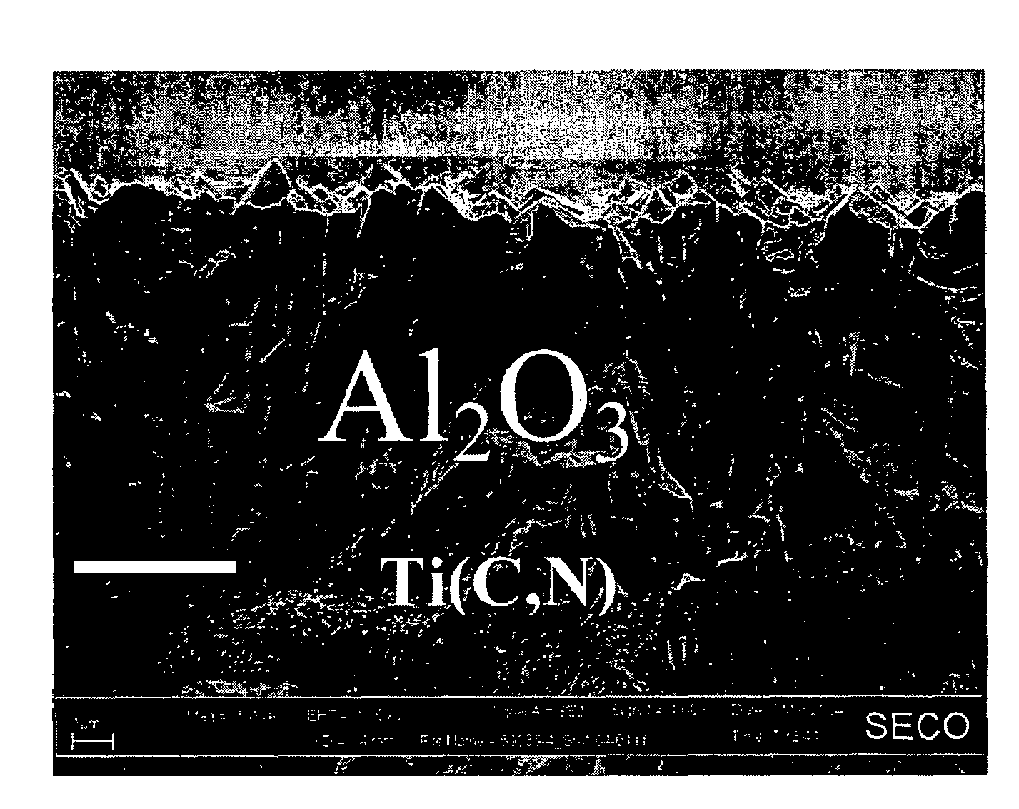
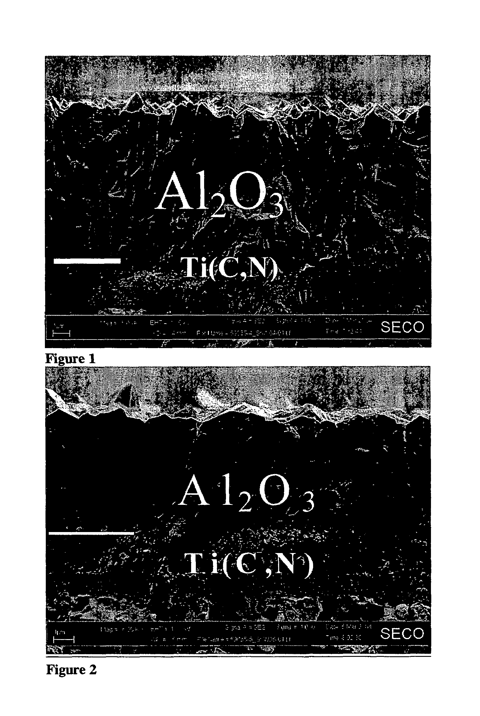
[0063]Layers a) and b) were studied using Scanning Electron Microscopy. The cross section images of the layers are shown in FIGS. 1 and 2, respectively. The differences in microstructure and morphology are clear.


PUM

PropertyMeasurementUnit
thicknessaaaaaaaaaa
thicknessaaaaaaaaaa
thicknessaaaaaaaaaa

Abstract

A new and refined method to produce α-Al2O3 layers in a temperature range of from about 750 to about 1000° C. with a controlled growth texture and substantially enhanced wear resistance and toughness than the prior art is disclosed. The α-Al2O3 layer of the present invention is formed on a bonding layer of (Ti,Al)(C,O,N) with increasing aluminium content towards the outer surface. Nucleation of α-Al2O3 is obtained through a nucleation step being composed of short pulses and purges consisting of Ti / Al-containing pulses and oxidising pulses. The α-Al2O3 layer according to the present invention has a thickness ranging from about 1 to about 20 μm and is composed of columnar grains. The length / width ratio of the alumina grains is from about 2 to about 12, preferably from about 4 to about 8. The layer is characterized by a strong (104) growth texture, measured using XRD, and by low intensity of (012), (110), (113), (024) and (116) diffraction peaks.

Description

BACKGROUND OF THE INVENTION[0001]The present invention relates to a coated cutting tool insert designed to be used in metal machining. The substrate is a cemented carbide, cermet, ceramics or cBN on which a hard and wear resistant coating is deposited. The coating exhibits an excellent adhesion to the substrate covering all functional parts thereof. The said coating is composed of one or more refractory layers of which at least one layer is a strongly textured alpha-alumina (α-Al2O3) deposited in the temperature range of from about 750 to about 1000° C.[0002]A crucial step in the deposition of different Al2O3 polymorphs is the nucleation step. κ-Al2O3 can be grown in a controlled way on {111} surfaces of TiN, Ti(C,N) or TiC having the fcc structure. TEM has confirmed the growth mode which is that of the close-packed (001) planes of κ-Al2O3 on the close-packed {111} planes of the cubic phase with the following epitaxial orientation relationships: (001)κ / / (111)TiX; [100]κ / / [112]TiX. A...

Claims


Application Information

Patent Timeline
Patent Type & Authority Patents(United States)
IPC IPC(8): B32B9/00C04BC23C16/02C23C16/40C23C16/455
CPCC23C16/029C23C16/403C23C16/45523Y10T428/24975Y10T428/265C23C16/30C23C30/005
Inventor RUPPI, SAKARI
Owner SECO TOOLS AB
Learn More