Low noise mixer with reduced distortion

a low-noise, mixer technology, applied in the field of mixers, can solve the problems of reducing the noise figure of the mixer, affecting the dynamic range of the mixer, and the structure has a disadvantage of a conflict between noise figure and linearity, and achieves the effect of significantly reducing the parasitic capacitan

Active Publication Date: 2008-11-04
MEDIATEK INC +1
View PDF4 Cites 11 Cited by
  • Summary
  • Abstract
  • Description
  • Claims
  • Application Information

AI Technical Summary

Benefits of technology

[0010]The present invention is to provide an improved low noise RF mixer. The mixer of the present invention has an excellent linearity due to reduction of a second-order distortion.
[0013]The inductor neutralizes the effect of parasitic capacitance induced at the common source junction of each switch pair of the switching stage. Accordingly, the second-order distortion mainly due the parasitic capacitance is significantly reduced.BRIEF DESCRIPTION OF THE DRAWINGS

Problems solved by technology

However, the mixer may induce noise into the receiver, so that the noise figure of the receiver is degraded.
In addition, linearity of the mixer affects the dynamic range of the receiver.
However, such a structure has a disadvantage of a conflict between noise figure and linearity.

Method used


Image

  • Low noise mixer with reduced distortion
  • Low noise mixer with reduced distortion
  • Low noise mixer with reduced distortion

Examples


Embodiment Construction

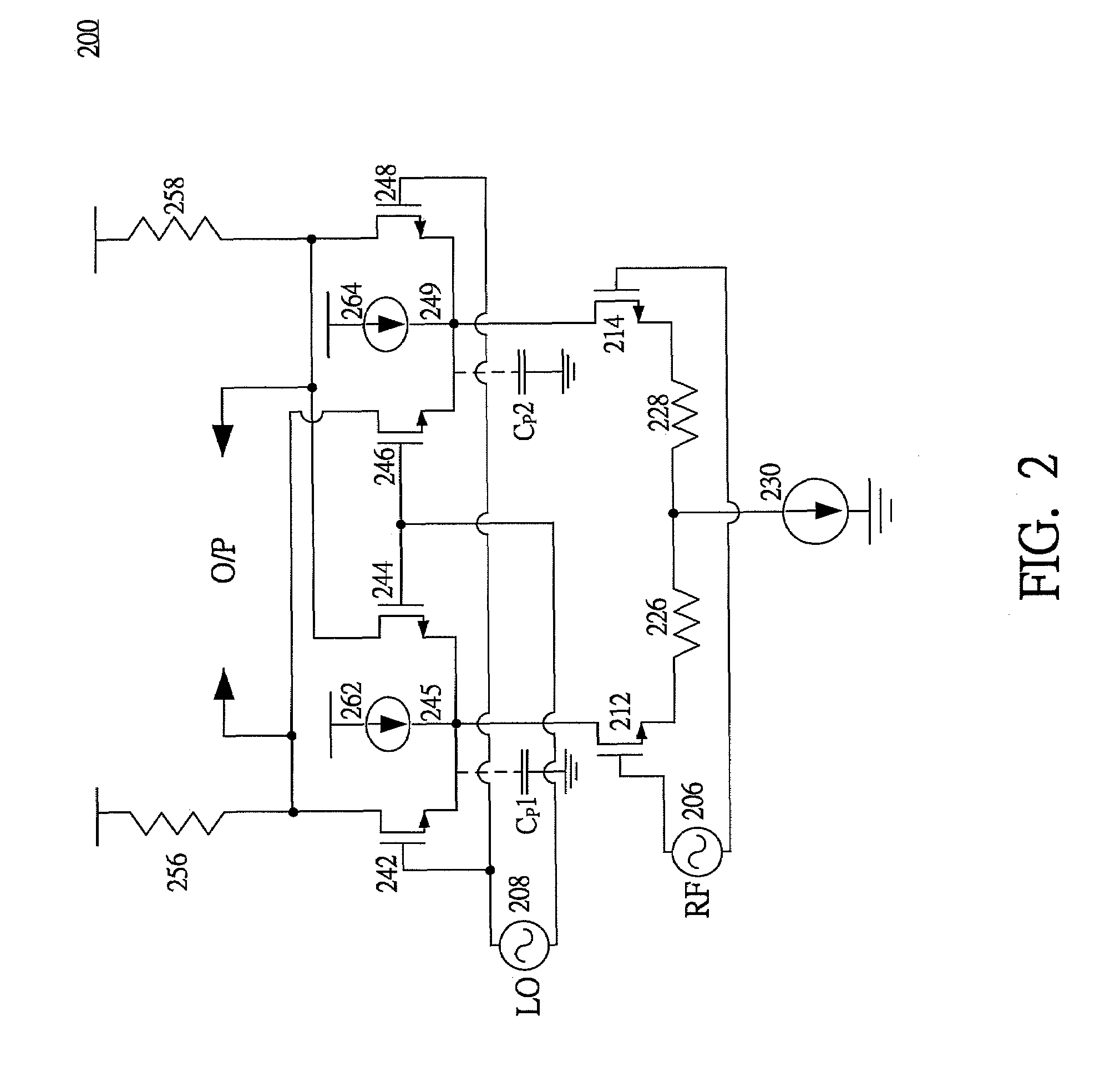
[0021]To improve the noise figure of the mixer, a method of current injection was proposed.

[0022]FIG. 2 shows a structure of a mixer 200. The mixer 200 is similar to the mixer 100 in FIG. 1, however, the mixer 200 is further provided with additional current injection. As shown, mixer 200 includes an inputting stage having a switch pair (transistors 212, 214) and a transconductance circuit consisting of degeneration resistors 226, 228 and a current source 230, a switching stage having two switch pairs (transistors 242, 244, and 246, 248), and a load stage constructed by resistors 256 and 258. The inputting stage is connected with an RF signal source 206, and the switching stage is connected with a local oscillation signal source 208.

[0023]In this example, the transistors are implemented by CMOS transistors.

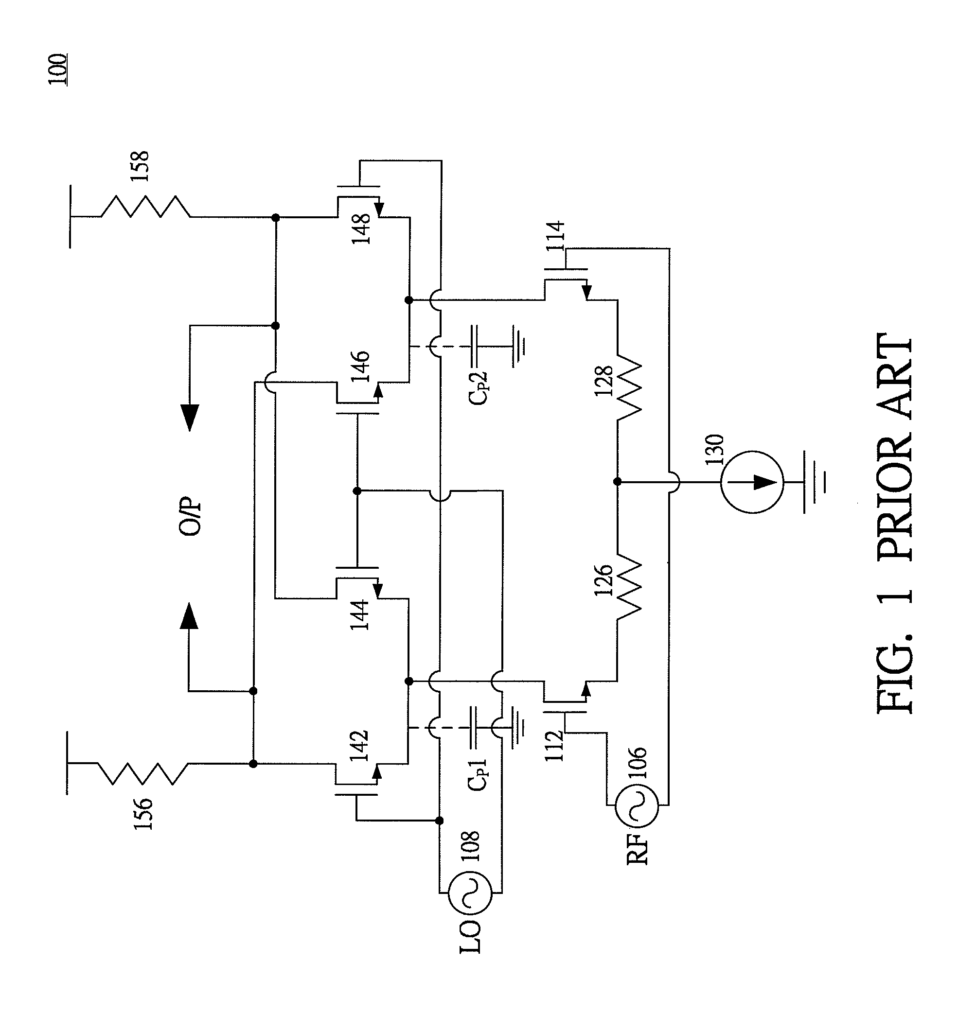
[0024]The elements mentioned above and connections thereof in the mixer 200 are similar to those of the mixer 100, and therefore the descriptions thereof are omitted to avoid redun...


PUM


Abstract

A low noise RF mixer is described. The mixer of the present invention has excellent linearity due to reduction of second-order distortion. The mixer includes an inputting stage, a switching stage and a load stage. The inputting stage includes a switching pair and a transconductance circuit. The load stage is formed by resistors. The switching stage includes a switch quad (two switch pairs). Each switch pair of the switching stage has a current source for implementation of current injection to a common source (emitter) junction of the switch pair. For each switch pair of the switching stage, an inductor is connected between the current source and the common source (emitter) junction. In addition, a capacitor is connected with the inductor.

Description

TECHNICAL FIELD OF THE INVENTION[0001]The present invention relates to a mixer, more particularly, to an RF mixer suitable for use in high-frequency wireless communication applications, such as a direct conversion receiver operating in the order of GHz.BACKGROUND OF THE INVENTION[0002]A direct conversion technique is very suitable for high data rate applications, and therefore the technique is now widely used, such as a direct conversion receiver. In the direct conversion receiver, a mixer plays a very important role. The mixer converts an RF signal into an intermediate frequency (IF) or baseband signal. However, the mixer may induce noise into the receiver, so that the noise figure of the receiver is degraded. In addition, linearity of the mixer affects the dynamic range of the receiver. Therefore, various mixer structures are proposed in order to achieve desirable noise figure as well as linearity.[0003]FIG. 1 shows a structure of a conventional Gilber mixer 100. The mixer 100 inc...

Claims


Application Information

Patent Timeline
Patent Type & Authority Patents(United States)
IPC IPC(8): H04B1/28
CPCH03D7/1441H03D7/1433H03D7/1458H03D7/1491
Inventor CHUNG, YUAN-HUNG
Owner MEDIATEK INC
Why Eureka
Try Eureka