Semiconductor device and method for fabricating the same

a technology of semiconductors and semiconductors, applied in the direction of semiconductor devices, electrical devices, transistors, etc., can solve the problems of difficult to prevent the decrease of processing precision, the effect of reducing the capacitance, etc., and deteriorating, etc., to achieve the effect of reducing parasitic capacitance, high performance, and not impairing the effect of soi structur

Inactive Publication Date: 2008-11-11
FUJITSU SEMICON LTD
View PDF15 Cites 73 Cited by
  • Summary
  • Abstract
  • Description
  • Claims
  • Application Information

AI Technical Summary

Benefits of technology

[0024]According to the present invention, on a silicon layer formed on a substrate with an insulation layer formed therebetween in a first region, a lattice-relaxed silicon germanium layer is formed, and a tensile-strained silicon layer is formed on the lattice-relaxed silicon germanium layer, and on the silicon layer in a second region, a compression-strained silicon germanium layer is formed, whereby an NMOS transistor using the tensile-strained silicon layer as the channel, and a PMOS transistor using the compression-strained silicon germanium layer as the channel are formed. Thus, the integrated transistor of high performance can be provided without impairing the effects of the SOI structure, such as the parasitic capacitance decrease, the electric power saving, etc.
[0025]According to the present invention, it is not necessary to remove the insulation layer on the substrate, which allows the step between the height of the surface of the tensile-strained silicon layer in the first region and the height of the surface of the compression-strained silicon germanium layer to be set in a range where the processing precision of the fabrication process can be ensured.
[0026]According to the present invention, the compression-strained silicon germanium layer is formed on the silicon layer formed on the substrate with the insulation layer formed therebetween, an energy beam is applied to the compression-strained silicon germanium layer to thereby lattice-relax the compression-strained silicon germanium layer, whereby the strained state of the silicon germanium layer can be selectively controlled in a short period of time. When it is not so necessary to improve the characteristics of the PMOS transistor, both the NMOS transistor and the PMOS transistor can use the tensile-strained silicon layer as the channels.

Problems solved by technology

Accordingly, it is difficult to integrate the NMOS transistor and the PMOS transistor on one and the same substrate.
Because of no insulation layer below the compression-strained silicon germanium layer in the region where the PMOS transistor is to be formed, resultant disadvantages will be as follows.
First, because of no insulation film between the compression-strained silicon germanium layer to be used as the channel of the PMOS transistor and the silicon substrate, effects of decreasing the capacitance, etc., which are characteristic of the SOI structure, is deteriorated.
Accordingly, the flatness of the surface of the substrate cannot be ensured, which will make it difficult to prevent the decrease of the processing precision.
However, in order to lattice-relax the compression-strained silicon germanium layer, high-temperature and long-time thermal processing has been so far required.
Accordingly, even the semiconductor layer, etc. which require no heating are heated, and resultantly this thermal processing has often generated defects, changed impurity profiles, etc., which have decided the device characteristics.

Method used


Image

  • Semiconductor device and method for fabricating the same
  • Semiconductor device and method for fabricating the same
  • Semiconductor device and method for fabricating the same

Examples


first embodiment

A First Embodiment

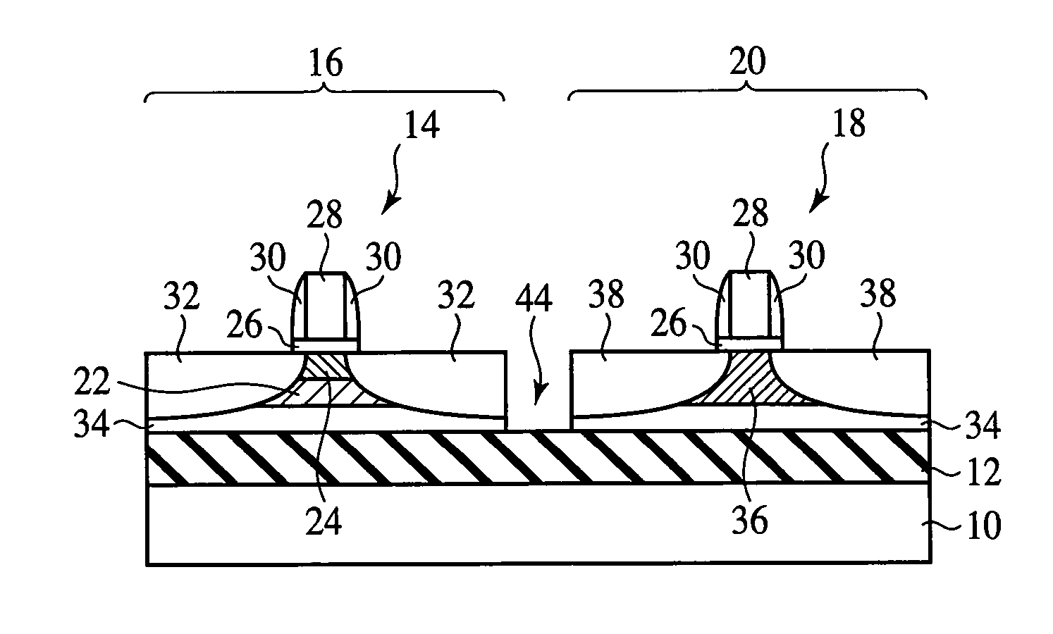
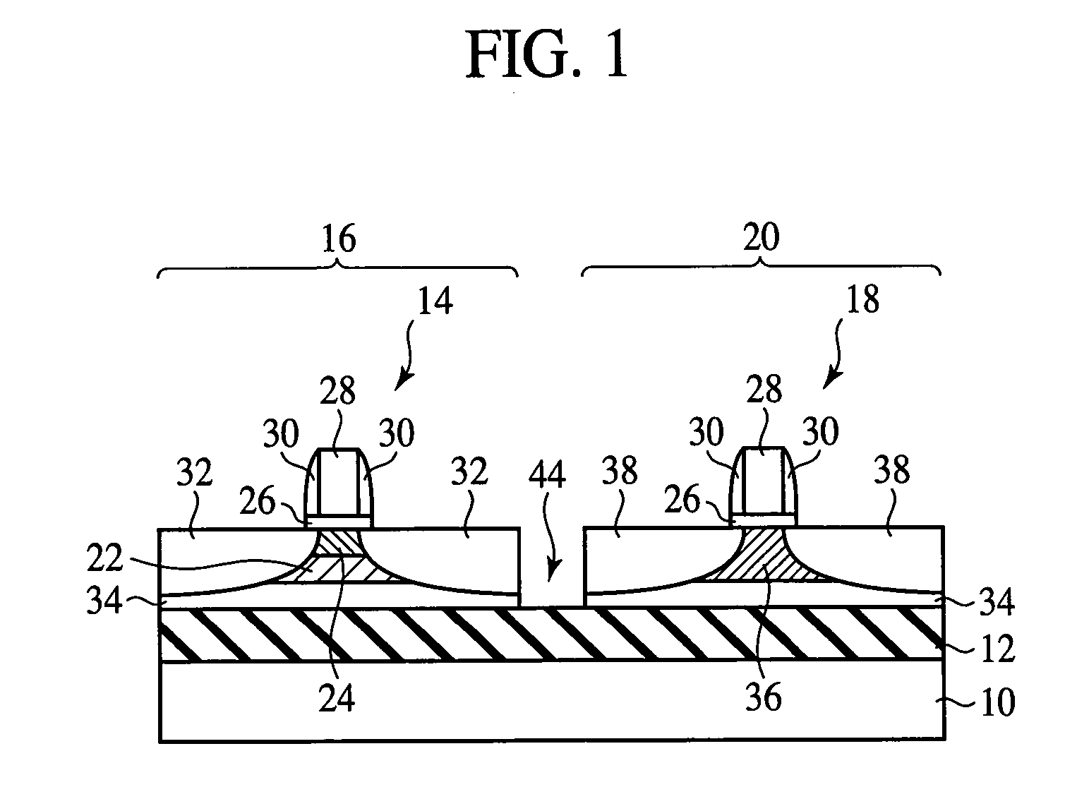
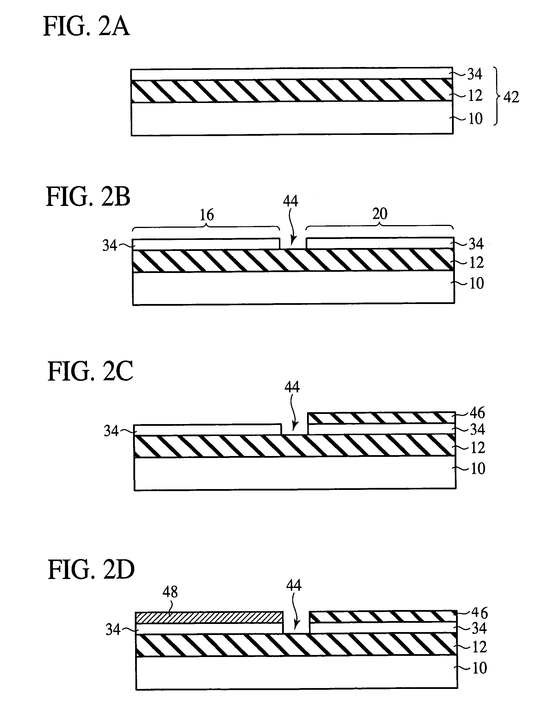
[0050]The semiconductor device and the method for fabricating the same according to a first embodiment of the present invention will be explained with reference to FIGS. 1 to 5D. FIG. 1 is a sectional view of the semiconductor device according to the present embodiment, which illustrates a structure thereof. FIGS. 2A to 5D are sectional views of the semiconductor device according to the present embodiment in the steps of the method for fabricating the same, which illustrate the method.

[0051]First, the structure of the semiconductor device according to the present embodiment will be explained with reference to FIG. 1.

[0052]An insulation layer 12 of silicon oxide film is formed on a silicon substrate 10.

[0053]On the silicon substrate 10 with the insulation film 12 formed on, an NMOS transistor region 16 where an NMOS transistor 14 is formed and a PMOS transistor region 20 where a PMOS transistor 18 is formed are provided. The NMOS transistor region 16 and the PMOS tr...

second embodiment

A Second Embodiment

[0101]The semiconductor device and the method for fabricating the same according to a second embodiment of the present invention will be explained with reference to FIGS. 6 to 8D. FIG. 6 is a sectional view of the semiconductor device according to the present embodiment, which illustrates a structure thereof. FIGS. 7A to 8D are sectional views of the semiconductor device according to the present embodiment in the steps of the method for fabricating the same, which illustrate the method. The same members of the present embodiment as those of the semiconductor device and the method for fabricating the same according to the first embodiment are represented by the same reference numbers not to repeat or to simplify their explanation.

[0102]The structure of the semiconductor device according to the present embodiment is basically substantially the same as that of the semiconductor device according to the first embodiment. The semiconductor device according to the presen...

third embodiment

A Third Embodiment

[0116]The method for fabricating the semiconductor device according to a third embodiment of the present invention will be explained with reference to FIGS. 9A to 15B. FIGS. 9A-9D and 14A-14D are sectional views of the semiconductor device according to the present embodiment in the steps of the method for fabricating the same, which illustrate the method. FIGS. 10A and 10B are graphs of the Raman spectra of the silicon germanium layer before and after the application of a laser beam. FIGS. 11A and 11B are views explaining the relationship between the thickness of the silicon oxide film and the reflectance of a laser beam. FIG. 12 is a view explaining the relationship between the wavelength of a laser beam and the lattice relaxation. FIG. 13 is a graph schematically showing the relationship between the thickness of the silicon germanium layer and the lattice relaxation by the application of a laser beam. FIGS. 15A and 15B are views of the evaluation results. The sam...


PUM


Abstract

On an insulation layer 12 formed on a silicon substrate 10, there are formed in an NMOS transistor region 16 an NMOS transistor 14 comprising a silicon layer 34, a lattice-relaxed silicon germanium layer 22 formed on the silicon layer 34, a tensile-strained silicon layer 24 formed on the silicon germanium layer 22 and a gate electrode 28 formed on the silicon layer 24 with a gate insulation film 26 formed therebetween and in a PMOS transistor region 20 a PMOS transistor 18 comprising a silicon layer 34, a compression-strained silicon germanium layer formed on the silicon layer 34 and a gate electrode 28 formed on the silicon germanium layer 36 with a gate insulation film 26 formed therebetween.

Description

CROSS REFERENCE TO RELATED APPLICATIONS[0001]This application is a Continuation of International Application No. PCT / JP03 / 09885, with an international filing date of Aug. 5, 2003, which designated the United States of America.TECHNICAL FIELD[0002]The present invention relates to a semiconductor device and a method for fabricating the same, more specifically, a semiconductor device comprising transistors using a tensile-strained silicon layer and a compression-strained silicon germanium layer, and a method for fabricating the same.BACKGROUND ART[0003]Recently, the heterostructure of silicon and silicon germanium is used for the higher performance of the MOS transistor using silicon.[0004]As one technique of improving the performance of the NMOS transistor, it is known to form a tensile-strained silicon layer on a lattice-relaxed silicon germanium layer to use the silicon layer as the channel. As methods of forming a lattice-relaxed silicon germanium layer are known the method of form...

Claims


Application Information

Patent Timeline
Patent Type & Authority Patents(United States)
IPC IPC(8): H01L21/8238H01L21/762H01L21/84H01L27/12H01L29/10H01L29/786
CPCH01L21/76281H01L21/76283H01L21/84H01L27/1203H01L29/1054H01L29/78687H01L29/78696H01L21/823807
Inventor OCHIMIZU, HIROSATOMISHIMA, YASUYOSHI
Owner FUJITSU SEMICON LTD
Why Eureka
Try Eureka