Automatic calibration of a three-axis magnetic compass

a three-axis magnetic compass and automatic calibration technology, applied in the direction of instruments, navigation instruments, surveying and navigation, etc., can solve the problems of inability to determine orientation when a user is stationary, gps is also susceptible to signal interruption, and the magnetic distortion field is not only due, so as to reduce computing power and memory, improve the accuracy of determining the distortion, and reduce the cost

Inactive Publication Date: 2008-11-18
P&I
View PDF23 Cites 159 Cited by
  • Summary
  • Abstract
  • Description
  • Claims
  • Application Information

AI Technical Summary

Benefits of technology

[0011]The user calibration in the instant invention can be for either 2 axis or 3 axis compasses. It is easier to determine the distortion for a 2 axis system which requires less computing power and memory. Hence, for certain applications where the system or device would be used in a level situation, it would be more cost effective to use a 2 axis system. For instance, in a vehicle, a 2 axis compass with 2 axis user calibration would be less expensive and still meet the accuracy requirements.
[0012]User calibration may not be limited to just one set of distortion correction coefficients for a device or system. A device or system may have capability to store multiple distortion correction coefficients to provide accurate compass readings in different device user modes. For instance, magnetic sensors read a different magnetic distortion field from a flip phone when the top is closed versus when it is open. Even with continuous distortion calibration, it may be difficult to have instantaneous, accurate compass readings each time the phone's top is opened and closed. A preferred implementation is to have 2 sets of distortion coefficients where the compass heading calculation would use one set of distortion correction coefficients when a cell phone top is closed and another when the top is open. A similar implementation would work if a device is being put in and out of vehicles; distortion correction coefficients for outside the car and distortion correction coefficients for inside the car. Having multiple distortion coefficients enables the compass to calculate a more accurate heading more quickly, if not instantaneously, in different situations.
[0013]In one embodiment,

Problems solved by technology

While GPS is excellent at determining location, it is unable to determine orientation when a user is stationary.
GPS is also susceptible to signal interruption, as the line of sight communication link to any given satellite may be broken by a building or even tree foliage.
In particular, GPS signals are not received through water; because of GPS communication reliability limitations.
Once inside the vehicle, the magnetic disto

Method used


Image

  • Automatic calibration of a three-axis magnetic compass
  • Automatic calibration of a three-axis magnetic compass
  • Automatic calibration of a three-axis magnetic compass

Examples


Embodiment Construction

)

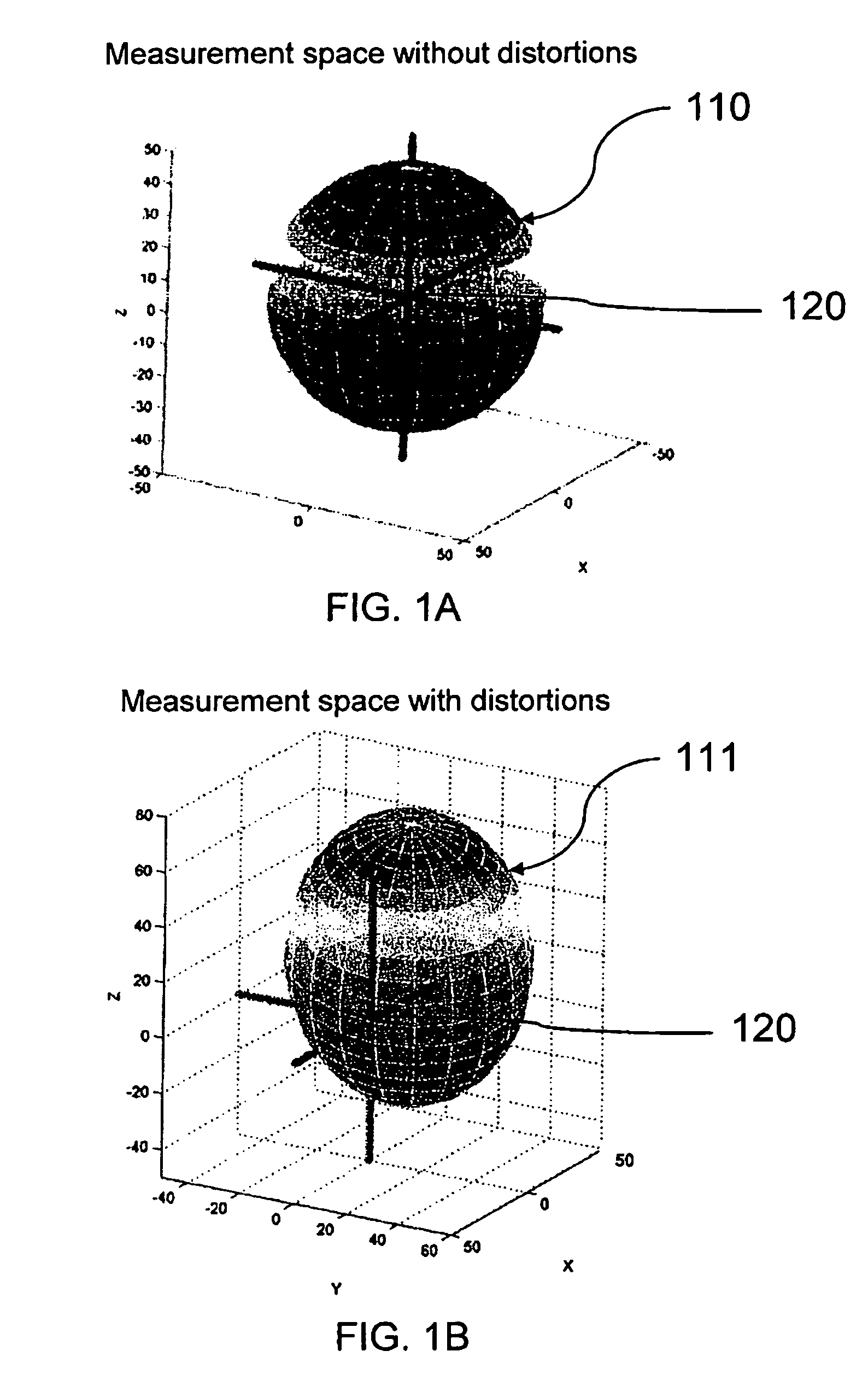
[0057]For magnetometers to be well calibrated for magnetic compassing, they must only sense Earth's magnetic field, and nothing else. With three magnetometers on three axes in an ideal situation, the measurements will seem to ride along the surface of a sphere of constant radius, herein referred to as a “measurement space.” The end-user may install a well calibrated module from a factory into an application whose magnetic environment contains distortions of a measurement space, and subsequently obtain a measurement with significant error in heading accuracy.

[0058]Two most common impairments to the measurement space are hard-iron and soft-iron distortions. The hard-iron distortion may be described as a fixed offset bias to the magnetometer readings, effectively shifting the origin of the ideal measurement space. It is usually caused by a permanent magnet mounted on or around the fixture of the compass installation and can be expressed as an offset vector H. Soft-iron distortion is a...


PUM


Abstract

A magnetic compass apparatus and method to account for magnetic distortion while determining a magnetic heading is disclosed. The method enables a compass module, comprising at least two magnetometers, to characterize its magnetic environment dynamically, while collecting data of a geomagnetic field; a user moves an apparatus through various orientations; the environment may or may not contain magnetic distortion influences. Data gathered by magnetometers and, optionally, accelerometers are processed through at least two filters before being transferred as a processed data set for repetitive measurement calculations. A series of calculations is executed recursively in time by solving one or more linear vector equations using processed data.

Description

BACKGROUND INFORMATION[0001]1. Field of Invention[0002]The invention relates generally to the determination of compass heading through the sensing of Earth's magnetic field, and more particularly to a method and an apparatus for use in magnetic compasses for the characterization of compass magnetic environment and compensation of the heading indications to account for local magnetic distortions.[0003]2. Cross-Reference to Related Documents[0004]The present invention is related in part to U.S. Pat. No. 4,851,775 entitled Digital Compass and Magnetometer Having A Sensor Coil Wound on a High Permeability Isotropic Core issued to Kim, et al. on Jul. 25, 1989, to U.S. Pat. No. 5,239,264 entitled Zero-Offset Magnetometer Having Coil and Core Sensor Controlling Period of an Oscillator Circuit issued to Timothy J. Hawks on Aug. 24, 1993, to U.S. Pat. No. 5,381,603 entitled Reference Pointer For a Compass Display issued on Jan. 17, 1995 to John S. Lee, to U.S. Pat. No. 6,243,660 entitled Dig...

Claims


Application Information

Patent Timeline
IPC IPC(8): G01C17/38
CPCG01C17/38
Inventor SODHI, RAJPRUNTY, JAYHSU, GEORGEOH, BECKY
Owner P&I
Why Eureka
Try Eureka