Controlled superheating of natural gas for transmission

a transmission and natural gas technology, applied in the direction of ratio control, multi-way valve, container discharging from pressure vessels, etc., can solve the problem that the fluid steam in the pipeline system cannot be maintained in the single-phase dry gas mode 100% of the time, shorten the life of the tape wrap, and reduce the cost of the external pipe wrap tape, so as to improve the reliability and accuracy of the dosage. , the effect of reducing the cos

Active Publication Date: 2008-11-18
SAUDI ARABIAN OIL CO
View PDF12 Cites 5 Cited by
  • Summary
  • Abstract
  • Description
  • Claims
  • Application Information

AI Technical Summary

Benefits of technology

[0039]The process of the invention minimizes the costs associated with corrosion inhibitor chemical dosing by 50% at GOSPs. It improves the reliability and accuracy of the dosage since the system is automated and human error is eliminated. In addition, the process h

Problems solved by technology

Operations of the system at temperatures above 130° F. proved to degrade the external pipe wrap tape, shortening the life of the tape wrap and necessitating its more frequent repair or replacement.
After this prior art gathering system was operated for many years, it was determined that the fluid steam in the pipeline system could not be ma

Method used


Image

  • Controlled superheating of natural gas for transmission
  • Controlled superheating of natural gas for transmission
  • Controlled superheating of natural gas for transmission

Examples


example

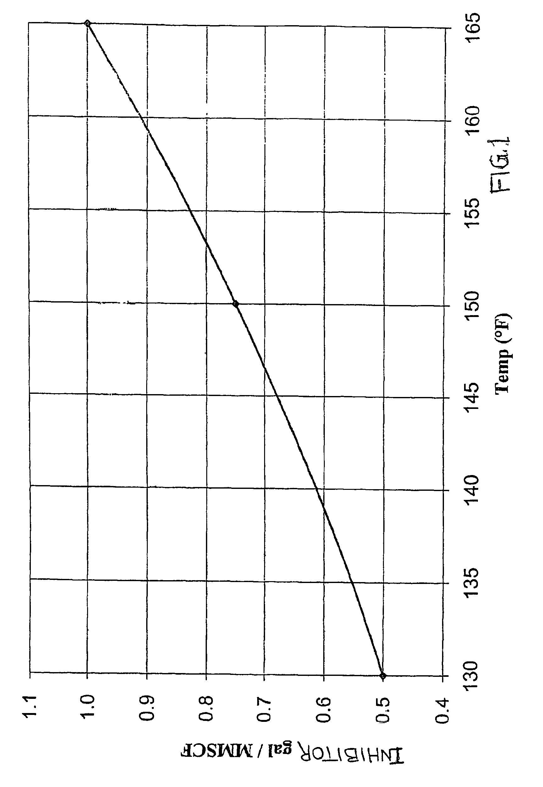
[0061]One week prior to the evaluation of the process of the invention, data collection was initiated at the six GOSPs and the GP test facilities for the purpose of comparing the conditions at the existing final gas temperature of 165° F. with the conditions of the superheat reduction process in accordance with the invention. The superheat reduction was started by reducing the exiting gas temperature setting from 165° F. to 130° F. at the six GOSPs feeding one separate pipeline network. This pipeline network terminated at a designated slug catcher drum at the gas plant. The object of the test was to quantify the amount of liquid removed from the pipeline at the gas plant. The protocol was conducted twice: first under desert summer conditions and then under desert winter conditions.

[0062]Four types of process data were gathered:

[0063]1. The amount of liquid collected at the GP slug catchers and its effect on GP operations.

[0064]2. The minimum superheat that GOSPs' operation must main...


PUM


Abstract

A method is provided for controlling superheating and temperature of a compressed natural gas stream and the addition of a corrision inhibitor composition for transmission through a pipeline that includes: a. dividing a stream of natural gas discharged from a high pressure gas compressor (106) into a first portion (108) and a second portion (202); b. passing the first portion (108) of the gas from the gas compressor to a heat exchanger (112) to heat the gas to a predetermined temperature; c. passing the first portion of gas (111) exiting the heat exchanger to an aftercooler (114); d. passing the second portion (202) of natural gas discharged from the gas compressor (106) to the aftercooler (114) without passing it through the heat exchanger (112), the second portion of gas and the first portion of gas being mixed at the aftercooler inlet and cooled by the aftercooler and discharged from the aftercooler as a cooled gas stream (116) having a temperature no greater than a first temperature; e. passing the cooled gas stream (116) from the aftercooler to a liquid discharge drum (118) to remove condensate from the cooled gas and discharging from the drum a partially dried gas stream (120) at a second temperature; f. passing the partially dried gas stream (120) from the discharge drum to the heat exchanger (112) in heat exchanging relation with the first portion of gas (108) from the gas compressor, and superheating at least a portion of the gas stream (120) to a third temperature to provide a superheated gas stream (129), the third temperature being controlled by an automated control loop responsive to a differential pressure across the gas compressor (106); and g. passing the superheated gas stream (129) into a transmission tie-line (256) and injecting a predetermined amount of a corrosion inhibitor composition into the tie-line to mix with the superheated gas stream, where the amount of corrosion inhibitor injected is proportioned in response to the third temperature.

Description

BACKGROUND OF THE INVENTION[0001]In natural gas transmission operations, wellhead fluids are processed in a gas-oil separation plant (GOSP), to produce dry crude, water, gas and hydrocarbon condensates. The wellhead fluids first enter a high pressure production trap (HPPT) where the gas and some of the water is separated from the crude oil. The remaining oil / water emulsion flows into a low pressure production trap (LPPT) where the oil is flashed at a lower pressure and more gas is separated. The oil / water emulsion is then pumped through a dehydrator and desalter to remove sufficient water and salt to produce product specification crude oil.[0002]The gas from the low pressure production trap is compressed to the pressure of the high pressure production trap and both streams of gas are combined, further compressed and sent to gas plants (GP). In the gas plants, the gas is sweetened to remove sulfur, and sale gas and NGL are produced.[0003]Historically, during the early stages of oil p...

Claims


Application Information

Patent Timeline
IPC IPC(8): C01B3/32C07C7/20F16K49/00F17D1/04F17D1/16G05D23/00F17CF17C7/02
CPCF17C7/02F17C2205/0323F17C2221/033F17C2223/0123F17C2223/036F17C2227/0157F17C2227/0302F17C2227/0337F17C2250/032F17C2250/0621F17C2250/0631F17C2250/0636F17C2260/024F17C2260/053F17C2265/015F17C2265/025Y10T137/6579Y10T137/87338Y10T137/2501Y10T137/0391
Inventor AL-KHALIFA, HANIDELEVAN, DONALD P.WILSON, TIMOTHY T.AL-ABDULLATIF, ABDULRAHMAN
Owner SAUDI ARABIAN OIL CO
Why Eureka
Try Eureka