
Dual-band reflective infrared thermal imaging system

a thermal imaging system and infrared thermal imaging technology, applied in the field of small form factor dual-band reflective infrared thermal imaging systems, can solve the problems of reducing the marketability affecting the image recognition capacity the limited material of the infrared thermal imaging system, so as to improve the image recognition capacity, reduce the manufacturing cost of the infrared thermal imager, and broaden the utilization of the infrared imag

Inactive Publication Date: 2008-11-18
UNIMEMS MFG
View PDF12 Cites 51 Cited by
  • Summary
  • Abstract
  • Description
  • Claims
  • Application Information

AI Technical Summary

Benefits of technology

"The present invention provides a dual-band reflective infrared thermal imaging system with a reflective optical module to reduce manufacture cost. The system includes an infrared thermal imager and a visible light video camera disposed at the central axis of the infrared thermal imager. The system can coaxially and synchronously take infrared images with the infrared thermal imager and the visible light images with the visible light video camera. The infrared thermal imager includes a reflective optical module, composed of a first reflector and a second reflector, and an infrared imaging sensor for taking the infrared images reflected by the reflective optical module and focused on the infrared imaging sensor. The system also includes a control module, a signal output module, and a power module. The dual-band reflective infrared thermal imaging system can improve image recognition capacity and broaden the utilization of the infrared thermal imager."

Problems solved by technology

Since infrared radiation can be absorbed by most materials in the world, a conventional lens material of the infrared thermal imaging system is limited to some materials having lower infrared absorptivity.
Accordingly, the conventional infrared lens of the infrared thermal imaging system is very expensive, decreasing the marketability of the infrared thermal imaging system.
Therefore, the image quality thereof is not as clear and distinguishable as an image taken by a visible light video camera.

Method used


Image

  • Dual-band reflective infrared thermal imaging system
  • Dual-band reflective infrared thermal imaging system

Examples


Embodiment Construction

[0019]The following description is of the best presently contemplated mode of carrying out the present invention. This description is not to be taken in a limiting sense but is made merely for the purpose of describing the general principles of the invention. The scope of the invention should be determined by referencing the appended claims.

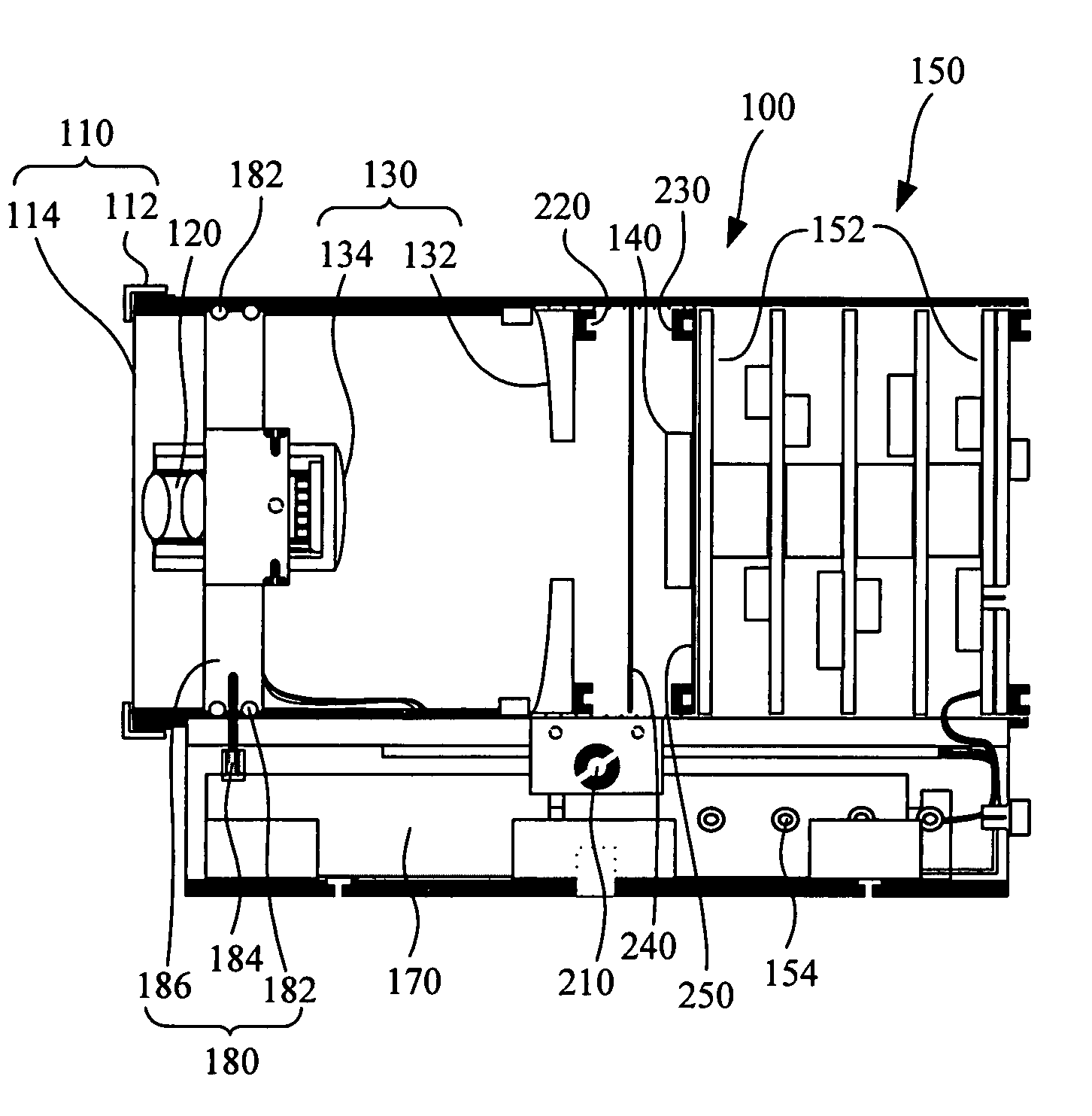
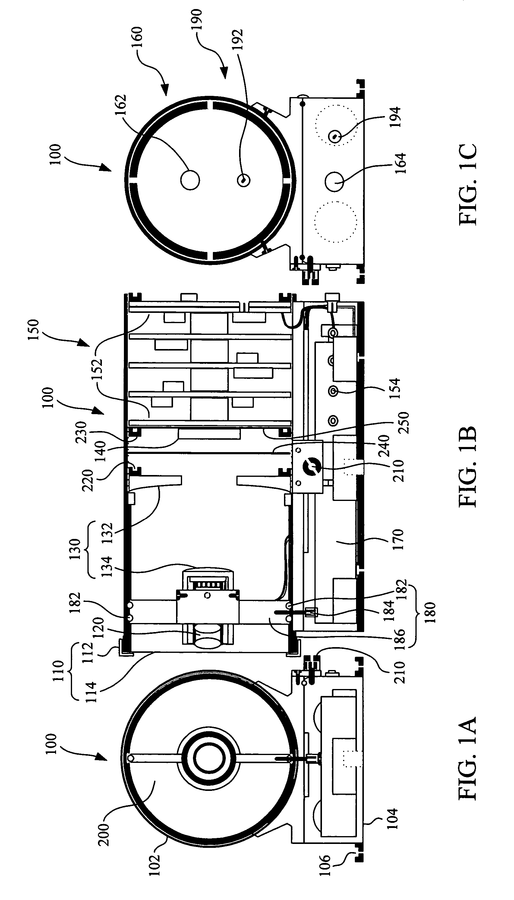
[0020]FIGS. 1A to 1C illustrate a schematic front view, side view, and rear view of a preferred embodiment of a dual-band reflective infrared thermal imaging system according to the present invention. The dual-band reflective infrared thermal imaging system 100 according to the present invention includes an infrared thermal imager 200 and a visible light video camera 120. The visible light video camera 120 is disposed at a central axis of the infrared thermal imager 200 and is preferably a refractive visible light video camera. Accordingly, the visible light video camera 120 can record images synchronously and coaxially with the infrared thermal ...


PUM


Abstract

A dual-band reflective infrared thermal imaging system is described. The dual-band reflective infrared thermal imaging system includes a reflective infrared thermal imager and a refractive visible light video camera. The refractive visible light video camera is configured at the central axis of the reflective infrared thermal imager so that the refractive visible light video camera and the reflective infrared thermal imager can synchronously and coaxially capture the images. The reflective infrared thermal imager further includes a reflective optical module and an infrared imaging sensor. The infrared images are focused on the infrared imaging sensor by way of the reflective optical module.

Description

RELATED APPLICATIONS[0001]The present application is based on, and claims priority from, Taiwan Application Serial Number 94115961, filed May 17, 2005, the disclosure of which is hereby incorporated by reference herein in its entirety.FIELD OF THE INVENTION[0002]The present invention generally relates to a reflective infrared thermal imaging system. More particularly, the present invention relates to a small form factor dual-band reflective infrared thermal imaging system.BACKGROUND OF THE INVENTION[0003]Due to rapid progress in the semiconductor industry and electronic technologies, technologies for manufacturing infrared measuring sensors have also progressed significantly. Infrared measuring sensors not only apply to the medical purpose of measuring body temperature but also apply to scientific, commercial and military purposes, such as laser detection, missile guidance, infrared spectrometry, remote control, burglarproofing equipment and thermal image detection. Conventionally, ...

Claims


Application Information

Patent Timeline
Patent Type & Authority Patents(United States)
IPC IPC(8): H01L31/02
CPCG01J5/04G01J5/08G01J5/0846G01J2005/0077
Inventor LEE, TZONG-SHENG
Owner UNIMEMS MFG
Learn More