
Mechanical self-reciprocating oscillator and mechanism and a method for establishing and maintaining regular back and forth movement of a micromachined device without the aid of any electronic components

a micromachined device and self-reciprocating technology, which is applied in the direction of mechanical roughness/irregularity measurement, instruments, printing, etc., can solve the problems of large footprint, occupying large space, and entail the additional overhead of power management and distribution

Active Publication Date: 2008-11-25
RGT UNIV OF MICHIGAN
View PDF2 Cites 14 Cited by
  • Summary
  • Abstract
  • Description
  • Claims
  • Application Information

AI Technical Summary

Benefits of technology

The system generates peak voltages exceeding 200 V with high energy efficiency, allowing for the direct powering of devices and integration into Microsystems using a low voltage DC source, while occupying minimal space.

Problems solved by technology

This requirement for high voltages is what prevents the use of these devices in integrated Microsystems and portable devices as they can only be powered by a single low-voltage DC supply.
These, however, occupy large footprints and entail the additional overhead of power management and distribution.
The miniaturization and integration of this high voltage generator has been limited by the need for an efficient inductive element as well as a high power, high voltage switch.
However, in standard CMOS technology transistors are severely limited by their dielectric and junction breakdown voltages, making them unsuitable for any application that demands even moderately high voltage or power levels [6].
The use of hybrid high voltage CMOS technology results in increased costs, and yet can handle only voltages up to about 80 V. In addition to the voltage limitation, transistors need electrical control signals that determine their switching characteristics.
The implementation of these oscillators using standard microelectronic circuits severely limits their voltage and power handling capacity and makes them unsuitable for direct use in any application demanding even moderately high voltages or power levels.

Method used


Image

  • Mechanical self-reciprocating oscillator and mechanism and a method for establishing and maintaining regular back and forth movement of a micromachined device without the aid of any electronic components
  • Mechanical self-reciprocating oscillator and mechanism and a method for establishing and maintaining regular back and forth movement of a micromachined device without the aid of any electronic components
  • Mechanical self-reciprocating oscillator and mechanism and a method for establishing and maintaining regular back and forth movement of a micromachined device without the aid of any electronic components

Examples


Embodiment Construction

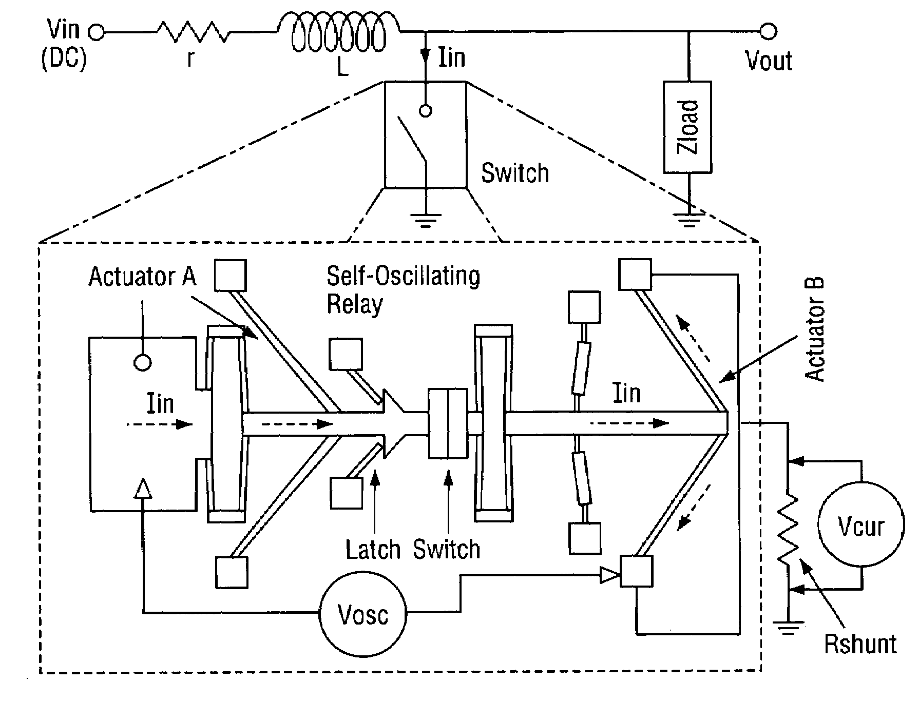
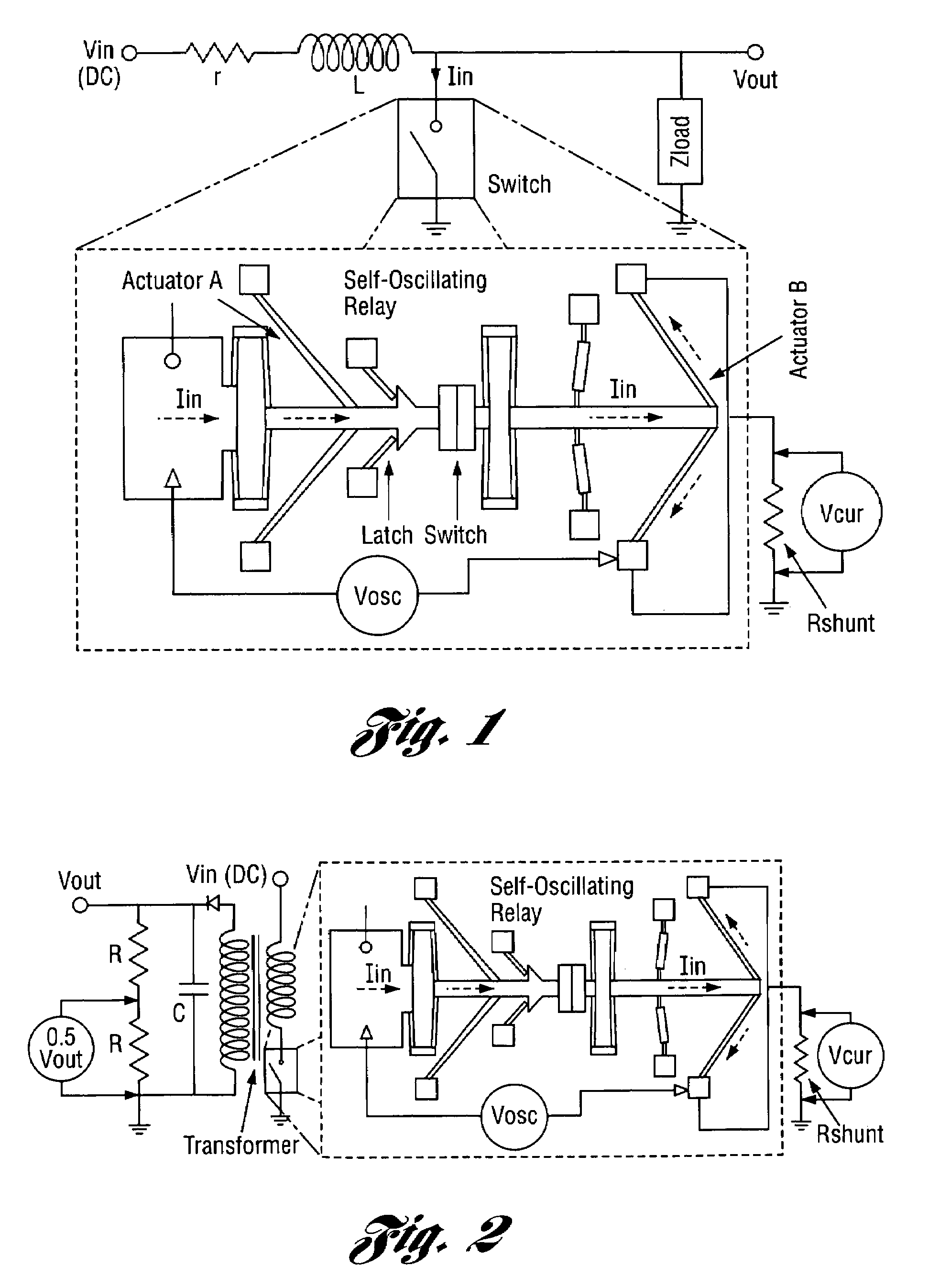
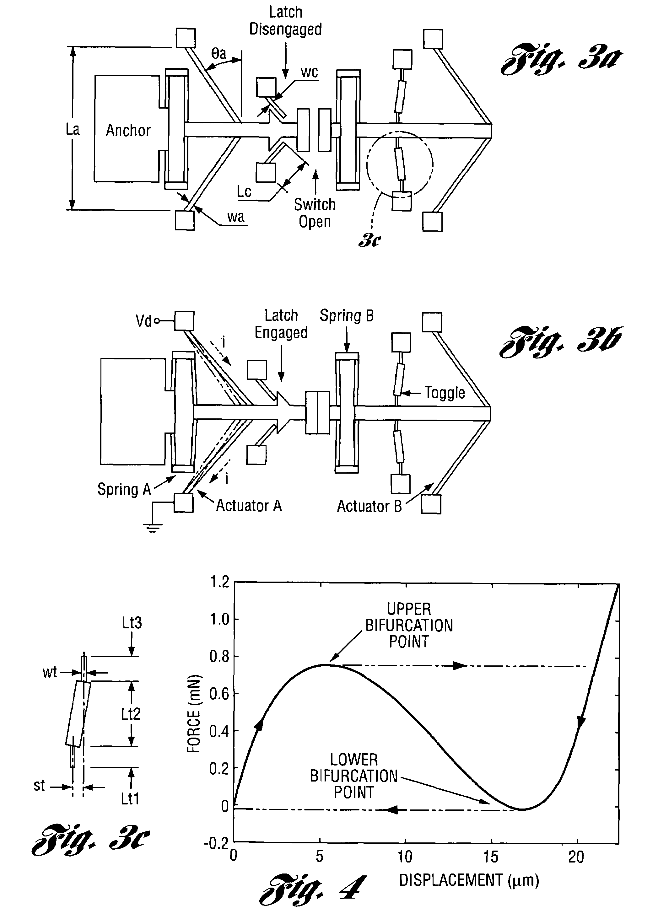
[0092]A mechanical self-reciprocating oscillator and mechanism and method for establishing and maintaining regular back and forth movement of a micromachined device without the aid of any electronic components are described herein. The oscillator and mechanism may operate within a fully mechanical self-oscillating relay and with an assembled wire wound inductive element. The oscillator and mechanism operate from a single DC power source. The operation of a high voltage generator utilizing the oscillator or mechanism has been implemented in two configurations. Experimental results show that the resulting microsystem can generate peak voltages in excess of 200 V.

[0093]The high voltage generator works on the principle of an induction coil voltage converter [9]. One embodiment of the microsystem, Version I, is similar to a boost converter [10] (FIG. 1). The current through an inductor is cut periodically by the action of a switch. In the portion of the operating cycle that the switch is...


PUM


Abstract

A mechanical self-reciprocating oscillator and mechanism and method for establishing and maintaining regular back and forth movement of a micromachined device without the aid of any electronic components are provided. The fully mechanical micromachined oscillator and mechanism are driven using only a DC power source on at least one substrate such as a semiconductor chip. The oscillator and mechanism preferably include an electrothermal actuator, that, when actuated, opens a switch to cut off supply current to the actuator. Two versions of the oscillator and mechanism are provided using distinct hysteresis mechanisms, one structural and the other thermal.

Description

CROSS-REFERENCE TO RELATED APPLICATION[0001]This application claims the benefit of U.S. provisional application Ser. No. 60 / 538,256, filed Jan. 22, 2004 and entitled “Microelectromechanical High Voltage Generator.”STATEMENT REGARDING FEDERALLY SPONSORED RESEARCH OR DEVELOPMENT[0002]This invention was made with Government support from the National Science Foundation under Contract No. EEC-9986866. The Government has certain rights in the invention.BACKGROUND OF THE INVENTION[0003]1. Field of the Invention[0004]This invention relates to mechanical self-reciprocating oscillators and mechanisms and methods for establishing and maintaining regular back and forth movement of a micromachined device without the aid of any electronic components.[0005]2. Background Art[0006]The following are related to the invention and may be referenced herein:[0007][1] W. Tang et al., “Electrostatic Comb-Drive of Lateral Polysilicon Resonators,” SENSORS AND ACTUATORS A (PHYSICAL), v A21, n 1-3, February 199...

Claims


Application Information

Patent Timeline
Patent Type & Authority Patents(United States)
IPC IPC(8): H02N10/00G01B7/34H03B5/30H02N1/00F03G7/06H02M3/16
CPCF03G7/06F05B2250/82H02M3/16
Inventor GIANCHANDANI, YOGESH B.UDESHI, KABIR
Owner RGT UNIV OF MICHIGAN
Learn More