Electronic control for a hydraulically driven generator

a technology of electric control and hydraulic system, applied in the direction of electric generator control, machine/engine, electric propulsion mounting, etc., can solve the problems of difficulty in maintaining precise frequency output control, engine speed variations wreak havoc, engine electrical power, etc., to prolong the life of the system and reduce warranty returns and costs.

Inactive Publication Date: 2008-12-02
UUSI
View PDF14 Cites 27 Cited by
  • Summary
  • Abstract
  • Description
  • Claims
  • Application Information

AI Technical Summary

Benefits of technology

[0009]Accordingly, it is an aspect of the present invention to provide a hydraulic control system for generating precise electrical output characteristics, particularly frequency output, along with prolonging the life of the system, thus reducing warranty returns and costs associated therewith.
[0021]Further, the method of operating the hydraulic control system may include preventing over-temperature damage to the hydraulic system when sensed fluid temperature exceeds safe operating temperature. Preventing over-temperature damage may involve annunciating the existence of over-temperature conditions to an operator when a first high temperature is obtained, triggering a timer to begin counting down a specified time when a second high temperature is obtained, and bypassing all fluid flow to the motor when the timer has expired. Bypassing all fluid flow to the motor can involve opening an electronically controlled hydraulic proportional valve disposed within the fluid circuit such that fluid is directed entirely to a bypass conduit. Additionally, the method may include overriding the bypassing step upon receipt of an emergency override instruction from an operator to prevent shutdown and keep the system operating.

Problems solved by technology

However, numerous modules and devices for the vehicle as well as the engine require electrical power.
While this will indeed operate a generator, variations in engine speed will wreak havoc with characteristics of power output and therefore with equipment which is dependent upon stable voltage and frequency characteristics of electrical power.
However, such systems can have difficulty maintaining precise frequency output for controlling the most sensitive AC equipment and are often susceptible to premature mechanical failure.

Method used


Image

  • Electronic control for a hydraulically driven generator
  • Electronic control for a hydraulically driven generator
  • Electronic control for a hydraulically driven generator

Examples


Embodiment Construction

)

[0031]As required, detailed embodiments of the present invention are disclosed herein. However, it is to be understood that the disclosed embodiments are merely exemplary of an invention that may be embodied in various and alternative forms. Therefore, specific functional details disclosed herein are not to be interpreted as limiting, but merely as a representative basis for the claims and / or as a representative basis for teaching one skilled in the art to variously employ the present invention.

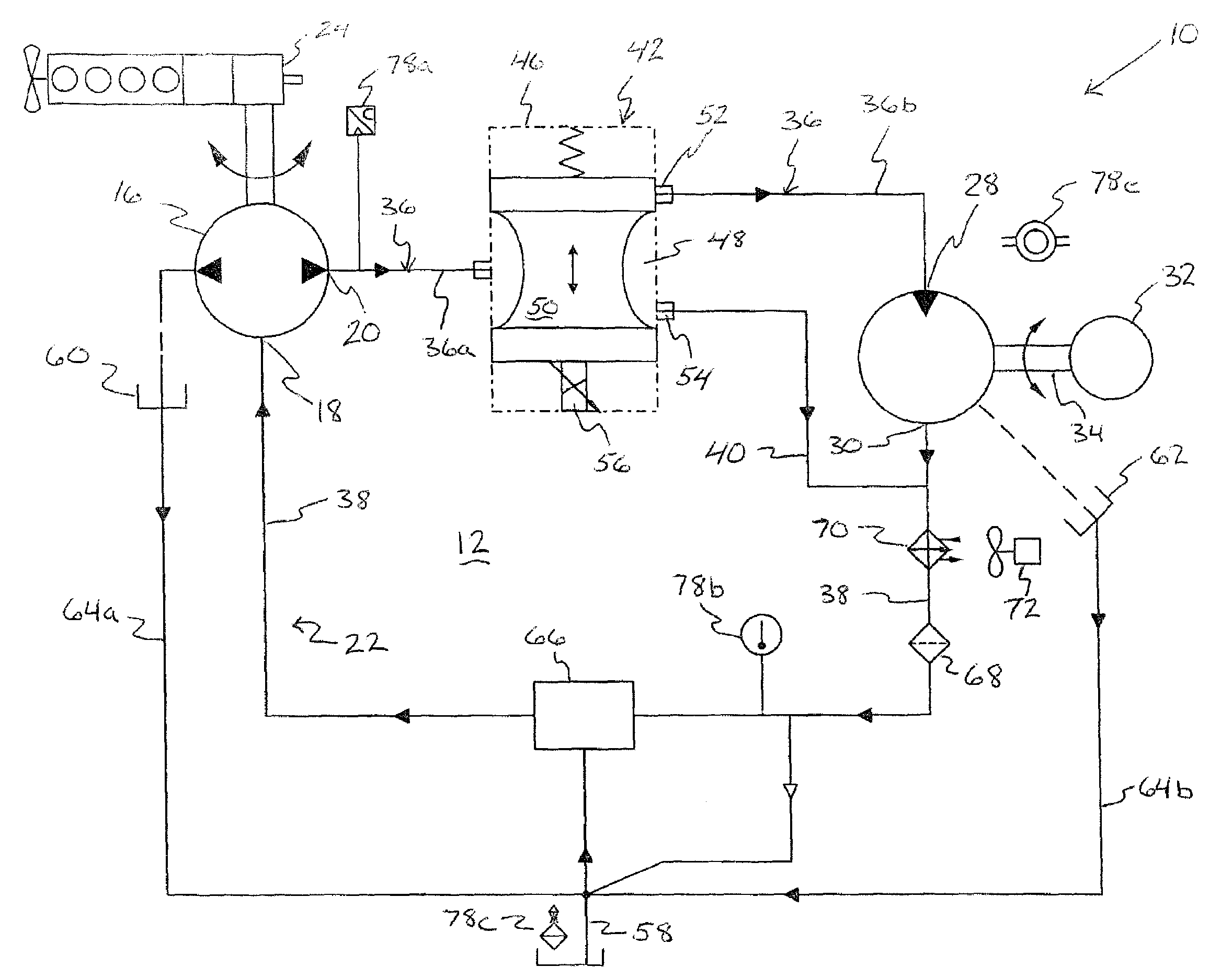
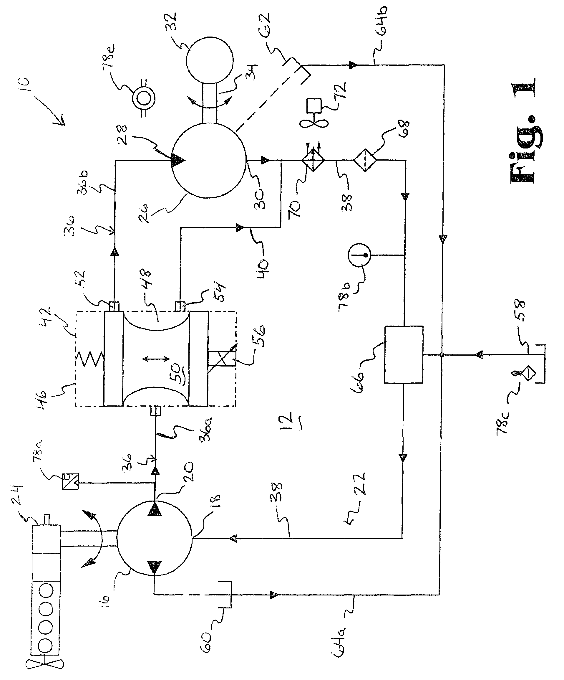
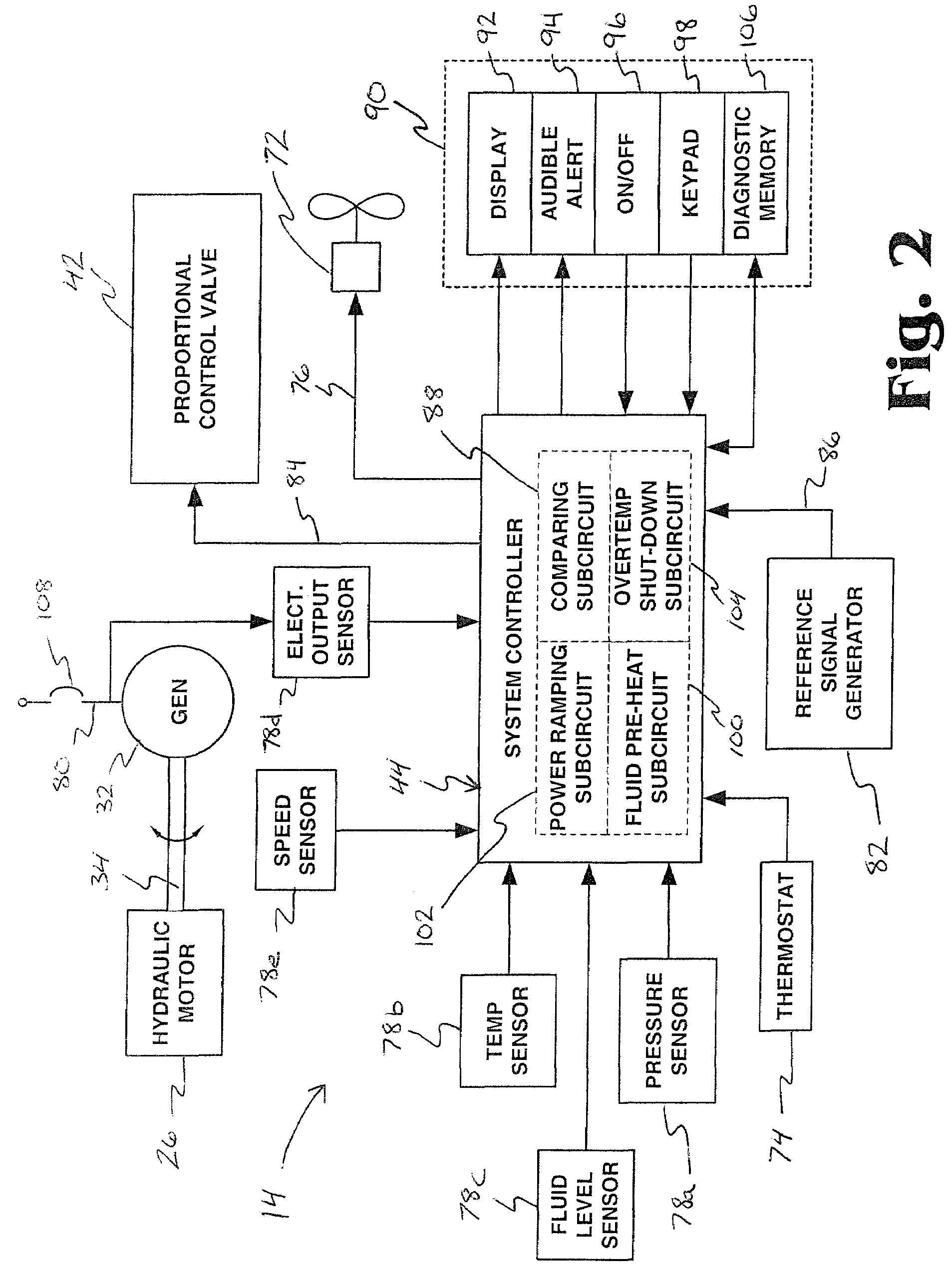
[0032]A hydraulic control system 10, according to an aspect of the present invention, is illustrated in FIGS. 1 and 2. FIG. 1 generally depicts a hydraulic circuit 12 for the hydraulic control system 10, while FIG. 2 generally depicts a control circuit 14 for the hydraulic control system 10.

[0033]Referring first to FIG. 1, the hydraulic circuit 12 of the system 10 is powered by a hydraulic pump 16, having an inlet 18 for receiving fluid for pumping and an outlet 20 for discharging pumped flu...


PUM


Abstract

Electronic control for a hydraulic system driving an auxiliary power source is provided, with specific application as a system for controlling the operation of a hydraulically driven AC generator. The system may includes a hydraulic pump, a hydraulic motor drivably connected to the generator, a fluid circuit for circulating fluid from the pump to the motor and back. The fluid circuit may contain a bypass conduit to bypass the motor. The system also includes a proportional servo control valve assembly for controlling the fluid circuits and a control circuit for controlling the proportional control valve assembly. The control system can be capable of controlling the flow of hydraulic fluid to the motor powering the electrical or mechanical system. Sensors for measuring the operating parameters of the system and an operator interface module can influence the operation of the system.

Description

CROSS-REFERENCE TO RELATED APPLICATIONS[0001]This application is a division of U.S. application Ser. No. 11 / 037,984 filed Jan. 18, 2005 now U.S. Pat. No. 7,053,498.BACKGROUND OF THE INVENTION[0002]1. Field of the Invention[0003]The present invention is directed to an electronic control for hydraulic system, and more particularly to precision control of hydraulically driven generators for stabilizing frequency and voltage output characteristics.[0004]2. Background Art[0005]Most engine driven vehicles utilize an internal combustion engine as the primary power source for propelling a vehicle. However, numerous modules and devices for the vehicle as well as the engine require electrical power. Typically, a rechargeable battery is provided with the vehicle as a basic power supply. The battery power supply system provides direct current (DC) electrical power for starting the vehicle engine and for operating certain DC compatible electrical loads when the vehicle is not running. The batter...

Claims


Application Information

Patent Timeline
Patent Type & Authority Patents(United States)
IPC IPC(8): F02D29/06
CPCF15B7/008F15B21/08F16H61/4035F16H61/4043F16H61/47F16H61/461F15B2211/20523F15B2211/20538F15B2211/40515F15B2211/413F15B2211/427F15B2211/45F15B2211/6333F15B2211/6336F15B2211/6343F15B2211/6656F15B2211/7058
Inventor BOISVERT, MARIO P.PERRIN, RANDALL L.PUSKA, MARVIN E.MITCHELL, JOHN E.
Owner UUSI
Why Eureka
Try Eureka