Miniaturized source devices for optical and mass spectrometry

a plasma source and micro-plasma technology, applied in the field of miniaturized plasma sources, can solve the problems of prohibitive analysis of a large number of samples, inability to take analytical equipment out of the lab for use in the field, and inability to use portable plasma sources that can be used in the field, etc., and achieve the effect of being convenient to make and opera

Active Publication Date: 2008-12-02
KARANASSIOS VASSILI
View PDF20 Cites 21 Cited by
  • Summary
  • Abstract
  • Description
  • Claims
  • Application Information

AI Technical Summary

Benefits of technology

[0008]The invention provides a low power consumption (<10 Watts), preferably battery-operated, low-flow rate (e.g., 10-350 mL / min), self-igniting, atmospheric pressure, portable, miniaturized plasma source device suitable for chemical analysis either in a laboratory or the field. The miniaturized plasma source device preferably has at least one dimension in the millimeter range. The invention also includes a micro plasma source device that preferably has at least one dimension in the micrometer or smaller range. For ease of description, the miniature and micro plasma source devices will be collectively referred to as miniaturized plasma source devices. The miniaturized plasma source devices may have one of a planar or tubular geometry, for example, and are inexpensive to make and to operate.
[0011]These miniaturized devices and interfaces are well-suited for environmental monitoring and provide other advantages. For instance, a miniaturized plasma source reduces power and gas consumption, thus also reducing operating cost. Furthermore, miniaturized plasma sources, especially if they are micro-fabricated, can be mass-produced thus also reducing manufacturing and purchasing costs. In addition to cost savings, the miniaturized devices can be embedded into other portable instruments, such as gas chromatography devices, to serve as detectors.

Problems solved by technology

However, analytical equipment cannot be taken out of the lab for use in the field.
Furthermore, analysis of a large number of samples is prohibitive due to the costs involved.
However, with this type of analytical equipment, the plasma source is typically tethered to a wall socket due to the high electrical power requirements of the equipment.
Further, the analysis equipment is firmly installed in the lab due its weight, size and gas consumption.
Due to the relatively large flow-rate and its associated cost, the typical ICP source uses Ar gas which is delivered from bulky and heavy containers, such as compressed-gas cylinders.
Furthermore, since a nebulizer can only be used with liquids, solids must first be converted to a liquid (e.g. digested using strong acids) prior to their introduction into an ICP source.
Because many analytical samples naturally occur as solids, and since acid digestion in the field is unlikely (due in part to safety concerns), use of a nebulizer for sample introduction into portable plasma sources that can be used in the field is unlikely.
Furthermore, because there are numerous applications in which very little sample is available for analysis, the requirement for a sample volume on the order of milliliters further restricts nebulizer applicability.
Additionally, pneumatic nebulizers have low sample introduction efficiency (˜1%), thus degrading detection limits.
However, some of the conventional microplasma sources require as much as 200 Watts of electrical power while others require vacuum pumps for proper operation, thus clearly preventing portability.
Others required use of high concentrations of a supporting electrolyte (e.g., 0.5 M HNO3 needed to make the pH approximately 1, thus possibly giving rise to contamination and making waste disposal an issue).
Both of these clearly disable portability.
But, there were difficulties with liquid sample introduction and poor sensitivities (in the 10,000 ppm range) were reported.
As well as, the device could not be used with gaseous or solid samples.
Overall, no microplasma sources have been developed that can be used with all three sample types: namely liquids, solids or gases.
Accordingly, conventional microplasma sources restrict analytical capability, utility and applicability by excluding the majority of analytical samples that naturally occur as liquids or solids.

Method used


Image

  • Miniaturized source devices for optical and mass spectrometry
  • Miniaturized source devices for optical and mass spectrometry
  • Miniaturized source devices for optical and mass spectrometry

Examples


example 1

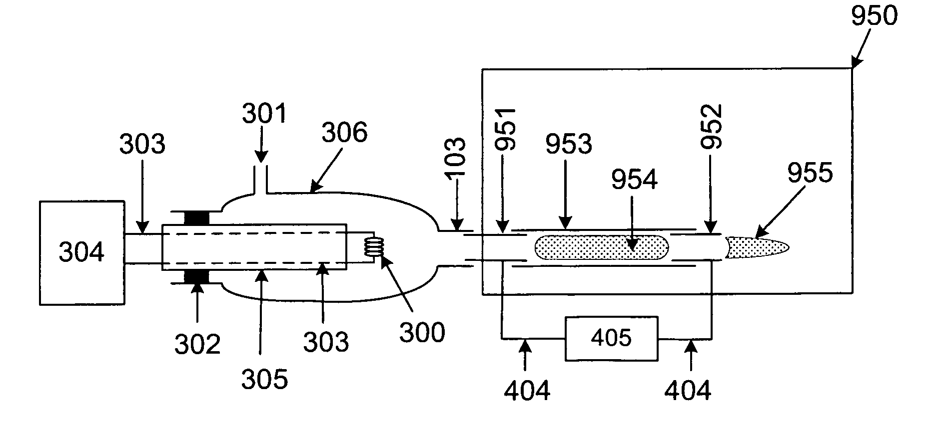
[0112]In this example, the planar microplasma source device 400 shown in FIG. 4 was used. The microplasma was generated by applying a potential difference of 3500 V DC across the electrodes 403. Both the miniaturized sample introduction device 102 and the microplasma source device 100 were operated as described previously. Briefly, 5 μL of a 1000 ppm standard stock solution of Na was pipetted onto the coiled filament 300 of the mini-ITV (described in FIG. 3). The solution was dried, the microplasma device 400 was turned on, the dried solution residue that remained on the coil 300 was vaporized and the 586 nm spectral line of Na was monitored in the time-domain. An example of a transient signal so obtained is shown in FIG. 21. Calibration curves were linear, detection limits were in the 100's of ppb and precision was at about 30%. In particular, device lifetime was a key concern since the microplasma source devices were unusable after about two hours of operation. The short lifetime ...


PUM


Abstract

Low-power, low flow-rate, portable, miniaturized plasma devices are provided. A portable, low-power, low flow-rate, miniaturized sample introduction device is also provided. The devices are inexpensive to make, have low operating cost and can be used with a variety of gases and gas mixtures. The devices can be used for elemental analysis from liquid or solid micro-samples by optical emission or mass spectrometry provided that an appropriate sample introduction system is used.

Description

CROSS REFERENCE[0001]This application claims priority from U.S. Provisional Application Ser. No. 60 / 550,052 filed on Mar. 5, 2004.FIELD OF THE INVENTION[0002]The invention relates to miniature and micro plasma devices suitable for chemical analysis either in a laboratory or in the field.BACKGROUND OF THE INVENTION[0003]Plasma sources are extensively used to generate photons or ions from sample analytes. In elemental analysis in particular, plasmas are extensively used as analytical tools for environmental monitoring. Due to health concerns, there is a need to improve the capability to monitor the environment. This involves analyzing a larger number of samples which typically occurs in the lab. However, in many cases, such as when accidental spills occur for example, improvements in monitoring the environment can be achieved by obtaining analytical results on-site (i.e. in the field) and in (near) real-time. However, analytical equipment cannot be taken out of the lab for use in the ...

Claims


Application Information

Patent Timeline
Patent Type & Authority Patents(United States)
IPC IPC(8): G01J3/30G01N1/10
CPCG01N21/67H01J49/0013H01J49/10H05H1/30G01N21/69G01N2021/0346G01N2201/0221
Inventor KARANASSIOS, VASSILI
Owner KARANASSIOS VASSILI
Why Eureka
Try Eureka