Modulation noise estimation mechanism

Active Publication Date: 2008-12-02
TEXAS INSTR INC
View PDF9 Cites 6 Cited by
  • Summary
  • Abstract
  • Description
  • Claims
  • Application Information

AI Technical Summary

Benefits of technology

[0016]Several advantages of the invention include the following. First, the invention, implemented as a very low gate count digital mechanism having no cost impact, eliminates the need for expensive test equipment that would otherwise be required during production to verify compliance with the modulation criteria set forth by the particular associated standard (e.g., Bluetooth radio specifications, etc). Second, the mechanism of the invention requires a relatively short test time as compared with prior art alternative solutions, which greatly reduces test costs and consequently semiconductor production costs. Third, the configurability of the mechanism permits flexibility in the test criteria to allow (a) adjustment of the tradeoff between test time and statistical significance of the results and/or (b) testing against various different criteria/standards the radio under test may be targeting.
[0017]Fourth, the testing with the mechanism of the present invention is unobtrusive as the test may be performed while the circuit operates on-line transmitting user data without causing any performance degradation. This enables the invention to be used in applications beyond production testing, such as dynamic adjustments of phase noise (e.g., through oscillator b

Problems solved by technology

This is because analysis preformed directly on the high frequency modulated signal is very difficult in practice.
Normally, modulation of the carrier is not possible in a closed loop scheme since the loop would see the modulation as a

Method used


Image

  • Modulation noise estimation mechanism
  • Modulation noise estimation mechanism
  • Modulation noise estimation mechanism

Examples


Embodiment Construction

Notation Used Throughout

[0030]The following notation is used throughout this document.

[0031]

TermDefinitionASICApplication Specific Integrated CircuitBISTBuilt-in Self TestBITBuilt-in TestDCDirect CurrentDCODigitally Controlled OscillatorDPLLDigital Phase Locked LoopDUTDevice Under TestIFIntermediate FrequencyFCWFrequency Command WordFPGAField Programmable Gate ArrayHDLHardware Description LanguageISIIntersymbol InterferenceISMIndustrial Scientific MedicalMNECModulation Noise Estimation CircuitMNEMModulation Noise Estimation MechanismnDCONormalized Digitally Controlled OscillatorPCPersonal ComputerPLLPhase Locked LoopRFRadio Frequency

DETAILED DESCRIPTION OF THE INVENTION

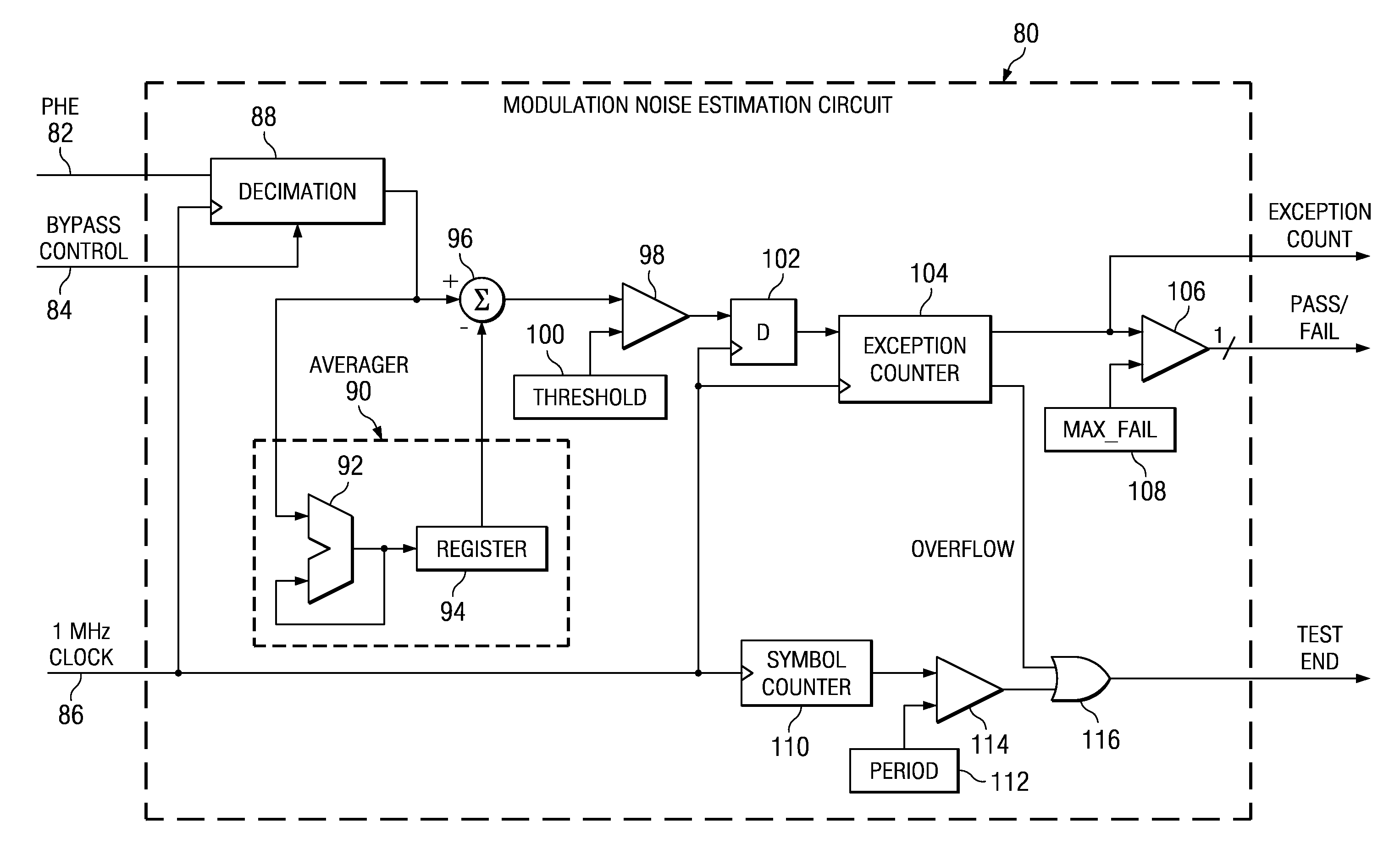
[0032]The present invention is a modulation noise estimation mechanism that functions to estimate the modulation noise present in a transmitter. The modulation noise estimation mechanism of the present invention is adapted to provide a pass / fail criteria thus reliably determining whether a component would qualify unde...


PUM


Abstract

An on-chip reduced complexity modulation noise estimation mechanism for performing nonlinear signal processing to analyze modulation noise to determine whether a semiconductor device under test complies with the performance criteria set by specifications or a standard corresponding thereto. When used in a two-point transmitter modulation architecture, the mechanism relies on the fact that the noise statistics at the output of the transmitter can be determined by observing the phase error output of the phase detector within the phase locked loop. In the digital embodiment of the mechanism, the phase error signal is compared to a configurable threshold value to generate an exception event. If the number of exception events exceeds a configurable max_fail value after comparisons of a configurable number of phase error samples, the test fails. A pass/fail signal is output reflecting the result of the test. The test comprises a configurable number of test samples to permit flexibility in the tradeoff between the time required to complete the test versus the statistical reliability of the test result, i.e. the probability of it correctly determining whether the tested device complies with target specifications.

Description

REFERENCE TO RELATED APPLICATIONS[0001]This application is based on U.S. Provisional Application Ser. No. 60 / 441,080, filed Jan. 17, 2003, entitled “Type-II-All-Digital PLL in Deep-Submicron CMOS”, incorporated herein by reference in its entirety.FIELD OF THE INVENTION[0002]The present invention relates to the field of data communications and more particularly relates to a phase modulation noise estimation mechanism suitable for on-chip use in digitally intensive radio transceivers such as those constructed according to the Bluetooth standard.BACKGROUND OF THE INVENTION[0003]Designing Built-in Test (BIT) or Built-In Self Test (BIST) capabilities into semiconductor devices (i.e. chips) is a well-known technique used to place the circuitry needed to perform critical performance tests directly on the chip rather than off chip. Without the built in test circuitry, external test equipment must be used to perform the various performance tests. Several limitations of using external test eq...

Claims


Application Information

Patent Timeline
IPC IPC(8): H04B3/20H03C3/06H03C3/09
CPCH03C3/0991H03C3/0941H03C3/095H03C3/0966H03L2207/50
Inventor ELIEZER, ORENSTASZEWSKI, BOGDANFRIEDMAN, OFER
Owner TEXAS INSTR INC
Why Eureka
Try Eureka