
Image forming method for the photothermographic material

a technology of photothermographic material and image forming system, which is applied in the field of photothermographic material, can solve the problems of insufficient image quality of medical images in the digital recording imaging material obtained by such a general image forming system, and the level at which it can replace medical silver salt film processed by conventional wet development,

Inactive Publication Date: 2008-12-09
FUJIFILM HLDG CORP +1
View PDF24 Cites 8 Cited by
  • Summary
  • Abstract
  • Description
  • Claims
  • Application Information

AI Technical Summary

Benefits of technology

The solution enables the production of high-quality images with soft gradation and reduced fogging, maintaining image preservability and stability, effectively addressing the limitations of existing materials by utilizing a dual-sensitivity silver halide system and high silver iodide content.

Problems solved by technology

While various kinds of hard copy systems using a pigment and a dye such as an ink-jet printer or electrophotography have been distributed as a general image forming system using such a digital recording imaging material, images in the digital recording imaging material obtained by such a general image forming system are insufficient in terms of image qualities required for medical images.
However, digital recording imaging material has not reached a level at which it can replace medical silver salt film processed by conventional wet development.
Since such a thermographic system using an organic silver salt has no fixing step and the photosensitive material contains all chemicals necessary for image forming, there has been an intrinsic problem in raw preservability, that is “increase in fog”, that an unexposed portion is blackened during storage from manufacture of a photosensitive material till the material is actually put into use, and another internal problem of “print-out”.
However the use of a silver halide with a high silver iodide composition has created a problem in that gradation is harder.

Method used


Image

  • Image forming method for the photothermographic material
  • Image forming method for the photothermographic material
  • Image forming method for the photothermographic material

Examples


example 1

[0474](Preparation of PET Support)

[0475]PET having IV (intrinsic viscosity) of 0.66 (measured in phenol / tetrachloroethane=6 / 4 (weight ratio) at 25° C.) was obtained according to a conventional manner using terephthalic acid and ethylene glycol. The product was pelletized, dried at 130° C. for 4 hours, melted at 300° C. Thereafter, the mixture was extruded from a T-die and rapidly cooled to form a non-tentered film having such a thickness that the thickness should become 175 μm after tentered and thermal fixation.

[0476]The film was stretched along the longitudinal direction by 3.3 times using rollers of different peripheral speeds, and then stretched along the transverse direction by 4.5 times using a tenter machine. The temperatures used for these operations were 110° C. and 130° C., respectively. Then, the film was subjected to thermal fixation at 240° C. for 20 seconds, and relaxed by 4% along the transverse direction at the same temperature. Thereafter, the chucking part were sli...

example 2

[0593]>

[0594]Preparations of photothermographic material-9 to -13 were conducted in the similar manner to the preparation of photothermographic material-1, except that two or more image forming layers was set as shown in Table 2, while a sample of the photothermographic material was produced by subjecting reverse surface of the back surface to simultaneous overlaying coating by a slide bead coating method in order of the image forming layer, intermediate layer, first layer of the surface protective layer and second layer of the surface protective layer starting from the undercoated face.

[0595]Other preparations and evaluations were executed in the similar manner to Example 1. Results are shown in Table 2. In the table, the layers are called from near side of the support; lower layer, middle layer and upper layer.

[0596]

TABLE 2Silver halide emulsionMixingPhotothermographicParticleratio bySensitivityγ valuematerialNo.size (nm)Ag molDmin logEDmaxD = 0.5D = 1.09upper layer75200.150.263.9...

example 3

[0598](Preparation of Silver Halide Emulsion-4)

[0599]To 1420 mL of distilled water was added 4.3 mL of a 1% by weight potassium iodide solution, further, added 3.5 mL of 0.5 mol / L sulfuric acid and 36.7 g of phthalated gelatin, and the resulted solution was kept at 42° C., while stirring in a stainless reaction bottle, and solution A prepared by diluting 22.22 g of silver nitrate in distilled water to give a volume of 95.4 mL and solution B prepared by diluting 11.1 g of potassium bromide and 6.6 g of potassium iodide in distilled water to give a volume of 103 mL, were added in their entireties to the solution, over 3 minutes. Then, 10 mL of a 3.5% by weight hydrogen peroxide aqueous solution was added, further, 10.8 mL of a 10% by weight benzimidazole aqueous solution was added. Further, solution C prepared by adding distilled water to 51.86 g of silver nitrate for dilution to 317.5 mL was added at constant flow rate in its entirety over 50 minutes and solution D prepared by diluti...


PUM

PropertyMeasurementUnit
grain sizesaaaaaaaaaa
grain sizeaaaaaaaaaa
temperatureaaaaaaaaaa

Abstract

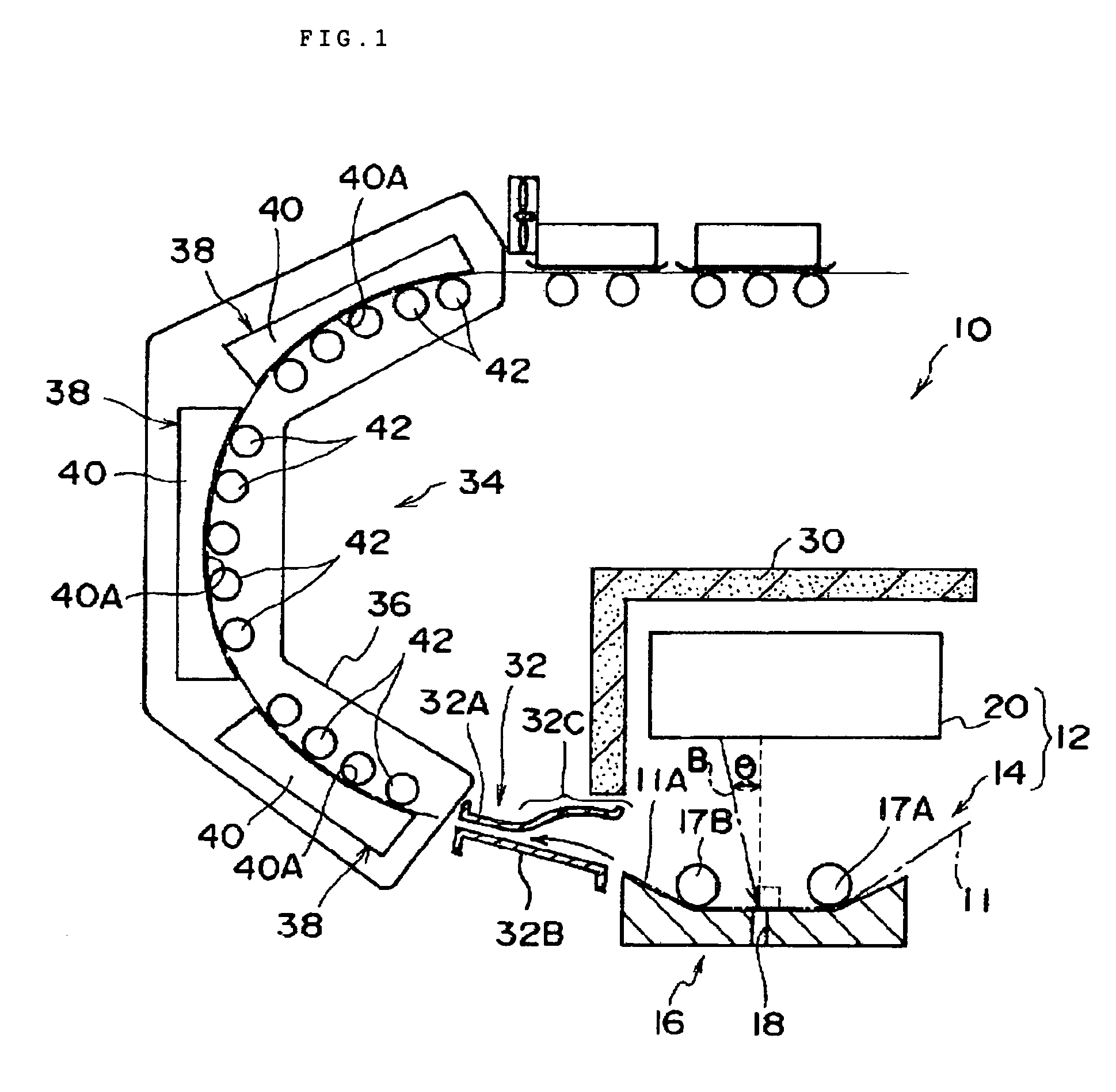
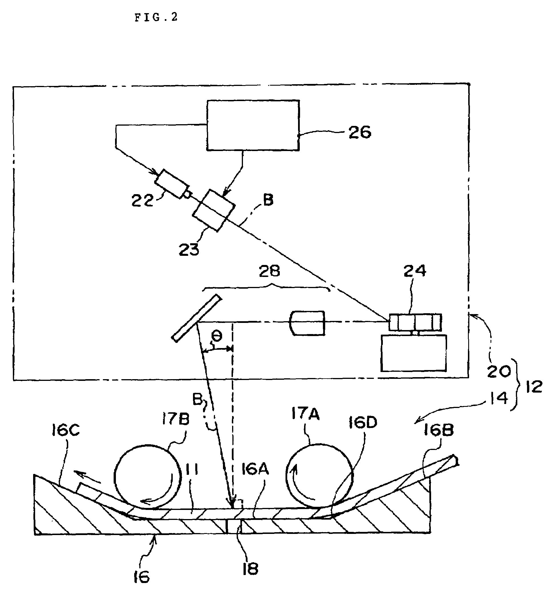
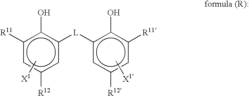
An image forming method comprising: imagewise exposing and thermal developing a photothermographic material using an image recording apparatus, wherein a part of the sheet is exposed and, in parallel with the exposure, development is started on a part of the sheet having been already exposed:wherein the photothermographic material comprises a reducing agent represented by formula (R), andwherein the photosensitive silver halide contains at least two preformed photosensitive silver halides having respective sensitivities different from each other for a light with the same exposure wavelength and a silver iodide content of the photosensitive silver halide is 40% by mole or more.

Description

CROSS-REFERENCE TO RELATED APPLICATION[0001]This application claims priority under 35 USC 119 from Japanese Patent Application Nos. 2002-303809 and 2003-26786, the disclosures of which are incorporated by reference herein. This application is a continuation-in-part of U.S. application Ser. No. 10 / 686,463, filed on Oct. 16, 2003 now abandoned, the disclosure of which is incorporated by reference herein.BACKGROUND OF THE INVENTION[0002]1. Field of the Invention[0003]The invention relates to a photothermographic material, and more particularly, to a photothermographic material revealing a soft gradation and stable in output image and an image forming method thereof.[0004]2. Description of the Related Art[0005]In the medical imaging field and the graphic arts field, there has been, in recent years, a strong desire for a dry photographic process from the viewpoints of environmental conservation and space-saving. Further the development of digitization has resulted in the rapid developmen...

Claims


Application Information

Patent Timeline
Patent Type & Authority Patents(United States)
IPC IPC(8): G03C5/16G03C1/498G03D13/00G03C5/02
CPCG03C1/49818G03C1/49881G03C1/49827G03C1/49845G03C1/49863G03C5/02G03C1/08G03C7/30541G03C7/3041G03C2001/03558G03C2001/03564G03C2200/36
Inventor OKA, YUTAKAOHZEKI, TOMOYUKI
Owner FUJIFILM HLDG CORP
Learn More