Localization element with energized tip

a technology of tissue localization and tip, which is applied in the field of tissue localization devices, can solve the problems of difficult cytologists' analysis of each sample, difficult-to-reliably-reach organ or tissue lesions, and severe limitations

Inactive Publication Date: 2008-12-23
TYCO HEALTHCARE GRP LP
View PDF319 Cites 31 Cited by
  • Summary
  • Abstract
  • Description
  • Claims
  • Application Information

AI Technical Summary

Benefits of technology

[0054]Further, this pusher assembly may be configured so that axial movement of the control lever will result in a corresponding axial movement of the pusher and the locator element. In this way, the locator element will reversibly extend through an aperture in a distal end of the delivery tube. The assembly may also be set up so that sufficient axial movement of the control lever may cause it to engage a detent disposed in t...

Problems solved by technology

Despite the advances made in technologies such as medical imaging to assist the physician in early stage diagnosis and treatment of patients with possible atypical tissue such as cancer, it is still often necessary to sample difficult-to-reliably-reach organ or tissue lesions by biopsy to confirm the presence or absence of abnormalities or disease.
Not only does this technique require multiple samples, but each sample is difficult for the cytologist to analyze as the specimen cells are isolated outside the context of healthy surrounding tissue.
Despite the advantages of wire focalization techniques to locate the suspect tissue for the surgeon, they have a number of severe limitations.
Such wires are often inaccurately placed and they cannot be removed except by surgical excision.
Even if a wire does not migrate after placement,...

Method used


Image

  • Localization element with energized tip
  • Localization element with energized tip
  • Localization element with energized tip

Examples


Embodiment Construction

[0078]Tissue localizing devices and locator elements having particular use in the present invention can have a variety of shape and configurations, including configuration such as those described in U.S. patent application Ser. No. 09 / 935,477, filed Aug. 22, 2001, PCT Application Serial No. PCT / US01 / 05013, filed Feb. 16, 2001, U.S. patent application Ser. No. 09 / 699,254, filed Oct. 27, 2000, U.S. patent application Ser. No. 09 / 613,686, filed Jul. 11, 2000, and U.S. patent application Ser. No. 09 / 507,361, filed Feb. 18, 2000, each of which is incorporated herein by reference in its entirety. These applications describe in detail various aspects of tissue localizing devices and methods for their deployment and excision.

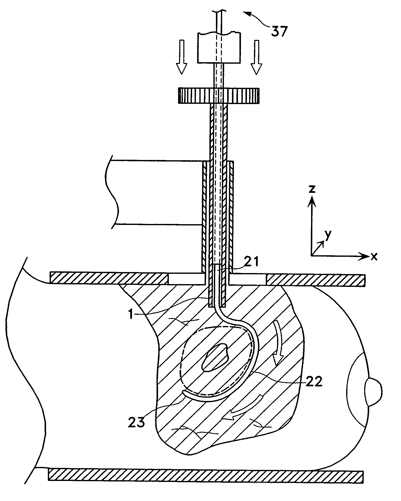
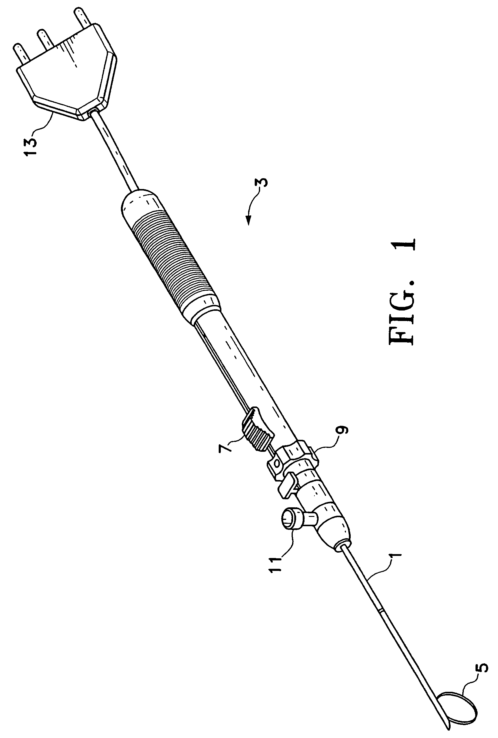
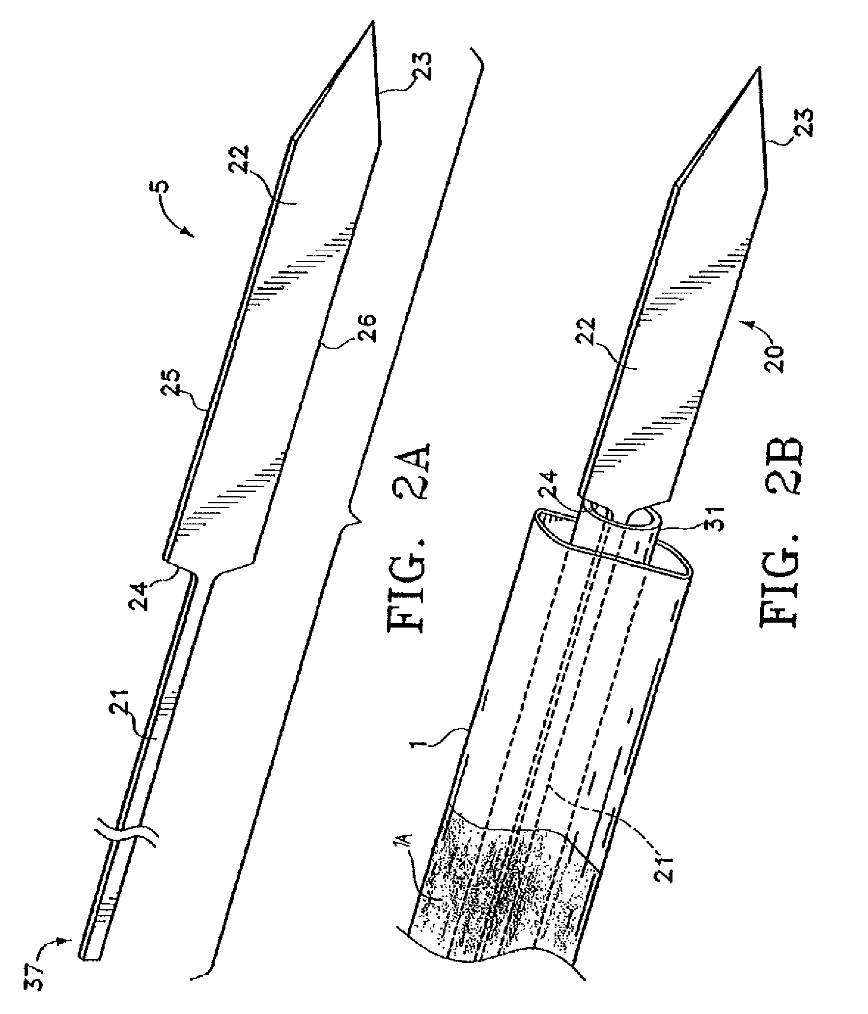
[0079]Referring to FIG. 1, a particular variation of a tissue-localizing device according to the present invention is illustrated. The device has a sleeve 1 extending from the pusher assembly 3. The inner surface of the sleeve is preferably, but not necessarily, covered...


PUM


Abstract

This invention is an improved tissue-localizing device with an electrically energized locator element for fixedly yet removably marking a volume of tissue containing a suspect region for excision. The electrical energizing of the locator element facilitates the penetration of the locator element in to subject's tissue and minimizes resistance due to dense or calcified tissues. At least one locator element is deployed into tissue and assumes a predetermined curvilinear shape to define a tissue border containing a suspect tissue region along a path. Multiple locator elements may be deployed to further define the tissue volume along additional paths defining the tissue volume border that do not penetrate the volume. Delivery of electric current may be achieved through monopolar or bipolar electronic configuration depending on design needs. Various energy sources, e.g. radio frequency, microwave or ultrasound, may be implemented in this energized tissue-localizing device.

Description

CROSS-REFERENCE TO RELATED APPLICATIONS[0001]This application is a continuation of application Ser. No. 10 / 271,850, entitled “Localization Element with Energized Tip” filed Oct. 15, 2002 now U.S. Pat. No. 6,752,767, which claims the benefit of U.S. Provisional Application No. 60 / 373,190, filed Apr. 16, 2002, and is related to co-pending U.S. patent application Ser. No. 10 / 272,314 entitled “Microwave Antenna Having a Curved Configuration” filed Oct. 15, 2002, and each of which is incorporated herein by reference in its entirety.FIELD OF THE INVENTION[0002]This invention relates generally to tissue-localizing devices and methods for their deployment and excision. More particularly, this invention relates to an improved tissue localizing device having an electrically energized locator element with ability to fixedly yet removably bound a tissue volume containing a region of interest, such as a nonpalpable lesion, foreign object, or tumor, preferably but not necessarily without penetrat...

Claims


Application Information

Patent Timeline
IPC IPC(8): A61B10/00A61B18/18A61B18/14A61B19/00
CPCA61B19/54A61B18/1477A61B18/1815A61B2018/1425A61B2018/1435A61B2018/1475A61B2018/183A61B2019/5408A61B90/39A61B2090/3908
Inventor TUROVSKIY, ROMANSU, TEDKIM, STEVENPRAKASH, MANI
Owner TYCO HEALTHCARE GRP LP
Why Eureka
Try Eureka