
Image determination apparatus and image determination method

Inactive Publication Date: 2008-12-23
NISCA KK
View PDF11 Cites 13 Cited by
  • Summary
  • Abstract
  • Description
  • Claims
  • Application Information

AI Technical Summary

Benefits of technology

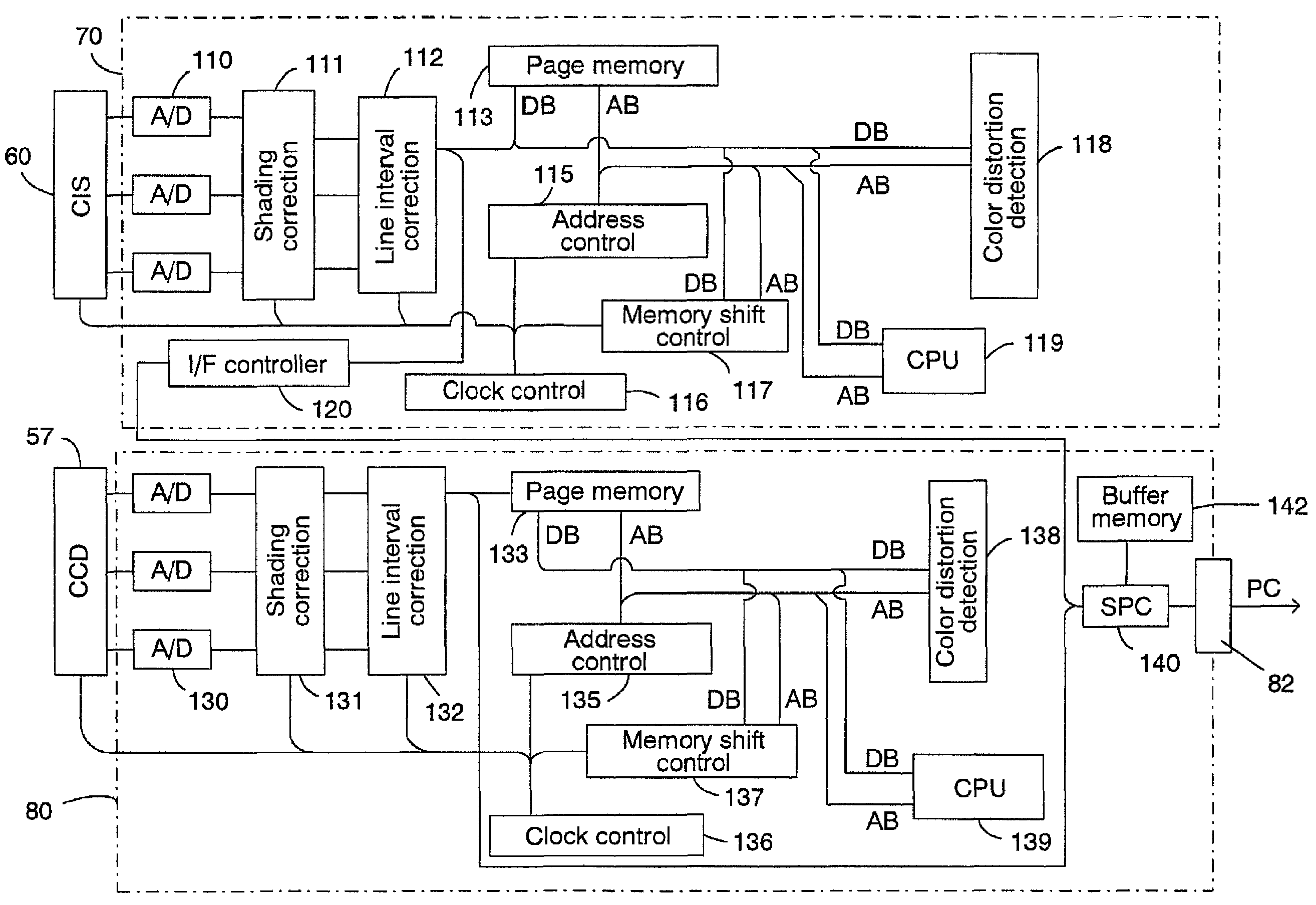
[0014]In order to achieve the above-mentioned objects, as the first aspect the present invention provides an image determination apparatus characterized by comprising an image data receiving means that receives image data comprising picture elements (pixels) formed from RGB (three primary colors of light), a first comparing means that compares a first color saturation value determined from color components of each pixel of the above-mentioned received image data to a first threshold value, a reversed image calculation means that calculates the color components of reversed images, or negative images, acquired by subtracting the above-mentioned color components from the maximum value of the color components of each of the above-mentioned pixels that can be obtained, a second comparing means that compares a second color saturation value determined from color components of this reversed image to a threshold value, and a color region determination means that determines whether there is color or monochrome based on the result of the comparison between the first comparing means and the second comparing means. Consequently, the present invention achieves region separation in order to simplify uneven divisions of color saturation values and obtain a simple processing circuit and achieve a region determination using programs as well as to quickly and easily detect high color saturation locations existing close to monochrome areas (none or low color regions) of color images.
[0015]In addition to the above-mentioned image determination apparatus, the present invention provides a brightness change detection means that finds color saturation values based on maximum values and minimum values in the color components of the above-mentioned pixels and then examines any changes in brightness from values of the color components of the pixels for regions the above-mentioned color region determination means has determined to be monochrome, an edge detection means that detects excessive change points in brightness obtained by comparing the detected value from the brightness change detection means and a specified value, a color saturation recalculation means that recalculates color saturation values at excessive change points in brightness detected by the edge detection means, and an error detection means that compares the result of the above-mentioned color saturation recalculation means to a specified value to determine errors in image data by counting the number of consecutive pixels which exceed a specified value. Consequently, the present invention achieves quick and easy detection of high color saturation locations existing close to monochrome areas (none or low color regions) of color images.
[0016]The second aspect of the present invention can also be an image determination apparatus characterized by comprising an image data receiving means that receives image data comprising picture elements (pixels) formed from RGB (three primary colors of light), a color conversion means that converts RGB color space of image data received by the image data receiving means to a uniform perceived color space that comprises brightness values in proportion to luminous intensity and standardized perceived color values in proportion to human coloring, an accumulation means that accumulates perceived color values of image data converted by the color conversion means in each small region comprised by specified pixels, and a color region determination means that determines whether the small regions are color or monochrome based on the accumulated value. Consequently, the present invention achieves region separation in order to simplify uneven divisions of color saturation values and obtain a simple processing circuit and achieve a region determination using programs as well as to quickly and easily detect high color saturation locations existing close to none or low color regions of color images.

Problems solved by technology

Sheet pass type color scanners which feed one sheet at a time from a stack of documents and then read the documents as they move through the scanner lack stability and have fluctuations in the images due to ripples and fluttering in the conveyance process of the documents or shocks caused by documents separating from the retaining point (nip point) of the transfer roller used to convey documents.
In addition, shapes containing false errors in the original picture also occur as image data.
When abnormal images, which are false pictures, are contained in original pictures at random locations within an image acquired in this manner (in particular, color distortions and color bleeding occurring at monochrome achromatic color areas), it is difficult to detect where these images exist, thereby increasing the desire for a definitive solution.
Because of this, when the document is not conveyed evenly, the read position on the image data will become inconsistent with the intervals in the composition of the image sensor, resulting in the occurrence of blurring in the image.
This method, however, requires the dispersion position to coincide with the positions of each color line of the image sensor, thereby requiring very precise adjustments which in turn leads to considerable manufacturing processes and in particular makes the adjustment process complicated making this an undesirable method.
In this disclosure, however, only the utilization of brightness for the method to detect black locations was disclosed while a detection method with good achromatic color accuracy is not.

Method used


Image

  • Image determination apparatus and image determination method
  • Image determination apparatus and image determination method
  • Image determination apparatus and image determination method

Examples


fifth embodiment

[0053]A method will be described that detects color distortion by calculating pixel coloring and negative pixel coloring and then specifying a region as a fifth embodiment that corresponds as a method in the embodiment of a first determination apparatus. An outline of the method that uses this color value is as follows.

[0054]Color distortions are noticeable when at least one color of a brightness value within RGB differs greatly from two other colors of a brightness value. Since the noticeable area is monochrome, the monochrome area is the target. The color distortion occurs in the direction of the paper feed and the influence of one error spreads to a number of pixels.

[0055]In other words, a large amount of color saturation occurs in border regions where the contrast within the monochrome regions changes greatly for pixels visible as color distortions when viewed by the human eye. Further, the determination of whether there is an original color image or a large amount of color satu...

sixth embodiment

[0072]An example using the CIE L*a*b* method will be described as the sixth embodiment as a method that corresponds to an embodiment of a second determination apparatus.

[0073]In this method color distortion is noticeable in monochrome areas of images. The color distortion is also noticeable in high contrast areas (edge areas) in images.

[0074]FIG. 6 shows an image read into a color scanner divided up depending on properties. The figure is a conceptual diagram showing image data distributed in two dimensions divided up into regions of each property. The figure is an enlarged view divided into color areas and monochrome areas.

[0075]Areas with high contrast (edge areas) exist in any of these. Areas with reading errors exist in the same manner but areas with conspicuous color distortion are in the slanted line area of FIG. 6.

[0076]In this method, generally, this slanted line area is detected in step (1) separation of color and monochrome, step (2) edge detection and step (3) color distor...

seventh embodiment

[0099]Next, the seventh embodiment corresponding to the method in the third determination apparatus will be described. This embodiment makes it possible to detect color distortion even if correlations are calculated within three primary colors.

[0100]In a correlation method, the next characteristic is focused on, and color distortion is detected. The target image, however, is limited to monochrome images. Consequently, the color and monochrome are separated in advance using the method already described, and the method described below will become applicable in regions where monochrome is recognized.

[0101]If, however, indications, such as a monochrome document, are given beforehand, the method can be applied even if the above-mentioned separation is not performed.

[0102]This method is realized on the assumption of the following properties.[0103](1) Color distortion is noticeable in high contrast areas in an image.[0104](2) Color distortion has different RGB brightness values.[0105](3) W...


PUM


Abstract

An image determination apparatus, an image reading apparatus, and an image determining method include a device for cutting a color / monochrome region based on a color saturation value obtained by a predetermined derivation method based on image data, and a device for detecting image errors located in large boundaries of brightness variations including color distortions based on correlations between color saturation and color. When errors are included in the image data acquired by, for example, a color image scanner due to primary color errors at random locations (in particular, color bleeding that occurs as a color distortion in monochrome achromatic color areas), it is possible to extract characteristics from the image data and detect locations in images where color distortions and color bleeding occur without using especially complicated and special compositions to detect where these errors occurred.

Description

BACKGROUND OF THE INVENTION AND RELATED ART STATEMENT[0001]The present invention relates to technology of apparatuses and methods which detect color bleeding and color distortions occurring adjacent to monochrome areas of pictures read while a transfer speed of a document is fluctuating, and relates to an image reading apparatus that reads documents while moving relative to the document and reading means, particularly the present invention comprises an image sensor that has, for example, a primary color sensor line and an image reading apparatus that simultaneously reads documents in three colors to acquire image data.[0002]As a single-package image sensor, there are so-called three-line color sensors that have three lines of sensors which are equipped with a primary color filter in the photoelectric transducers of each line. Not only can this three-line color sensor comprise an image reading apparatus (hereinafter referred to as color scanner) that reads color and be compact in siz...

Claims


Application Information

Patent Timeline
IPC IPC(8): G03F3/08G06F15/00G06K9/00G06T5/00H04N1/60
CPCG06T7/0004H04N1/6005H04N1/6027G06T2207/10008G06T2207/30144
Inventor HASHIGUCHI, SUMIHISAKAWAI, KEITAROUHIKOSAKA, NORIMASAMORITA, ATSUKOKUBOTA, MINEOTSUCHIYA, MITSUO
Owner NISCA KK
Learn More