Axial thrust bearing

a technology of axial thrust bearing and axial friction bearing, which is applied in the direction of sliding contact bearing, crankshaft, machine/engine, etc., can solve the problems of high thrust loss, increased damage to dirt particles, and certain tendency to fail, so as to increase the thickness of the lubricating gap, reduce wear, and build up additional hydrodynamic compressive force

Inactive Publication Date: 2008-12-30
MAN ENERGY SOLUTIONS SA
View PDF12 Cites 21 Cited by
  • Summary
  • Abstract
  • Description
  • Claims
  • Application Information

AI Technical Summary

Benefits of technology

[0019]The hydrodynamic pressure is built up as a result of the shear rate in the lubricating oil in conjunction with a converging lubricating gap proceeding in the direction of the shear rate. The shear rate in the lubricating oil consists of a circumferential component (because of the relative rotational movement) and a radial component (because of continuity). By providing the wedge surface with an additional orientation in the radial direction, advantage can be taken of the radial component of the shear rate to build up additional hydrodynamic compressive force. The result is an increase in the thickness of the lubricating gap and thus a reduction in wear.
[0020]So that the radial component of the shear rate can be used to build up additional hydrodynamic compressive force, it is both desirable and necessary for the wedge surface to have a radial orientation and for lubricating oil to flow away in the radial direction. Because of the radial orientation of the wedge surface, however, there is also a convergent lubricating gap in the radial direction, which effectively prevents an excessive throughput of lubricating oil.
[0021]An increase in the axial force brings about a reduction in the thickness of the lubricating gap and thus also in the volume flow rate of the oil in the case of an axial bearing with radially oriented wedge surfaces as well. For continuity reasons, however, the radial velocity component of the lubricating oil remains more-or-less constant. The decrease in the thickness of the lubricating gap causes the additional hydrodynamic compressive force being produced to increase. As a result of this relationship, the volume flow rate of the oil is not throttled as severely as it is in the case of a conventional axial bearing with a sealing web. The average temperature and viscosity of the lubricating oil are therefore less sensitive to increases in the axial force, and the danger of spontaneous failure is effectively reduced.

Problems solved by technology

The damaging effect of the dirt particles increases as the thickness of the lubricating gap decreases.
These bearings have a good load capacity, but because of the high shear rate, they also have high thrust losses and a certain tendency to fail “spontaneously” (see below).
This solution, too, suffers from the disadvantage that a design of this type also tends to fail spontaneously (see below).
The result is spontaneous failure, that is, the sudden collapse of the hydrodynamic compressive forces and the occurrence of mechanical contact between the thrust surfaces.

Method used


Image

  • Axial thrust bearing
  • Axial thrust bearing

Examples


Embodiment Construction

[0027]The exhaust gas turbocharger (not shown) consists essentially of the three housing parts, namely, a turbine housing, a bearing housing, and a compressor housing. In the known manner, a shaft is rotatably supported in the bearing housing by hydraulic radial bearings and also in axial thrust bearings, each of which is supplied with lubricating oil.

[0028]The special design of the axial thrust bearing is what is considered inventive within the scope of the object being described here, so that only the parts essential to an understanding of the invention are shown.

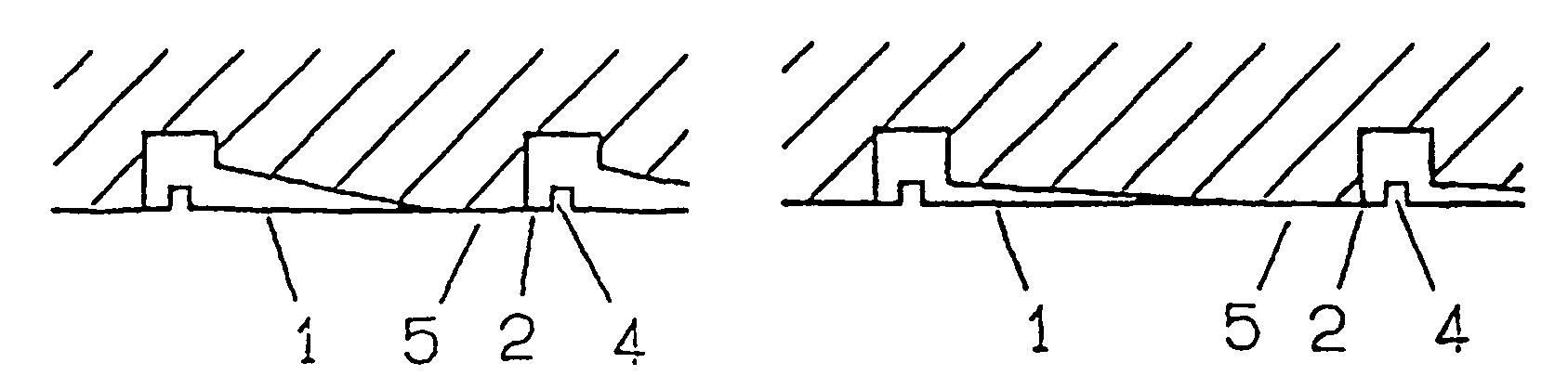
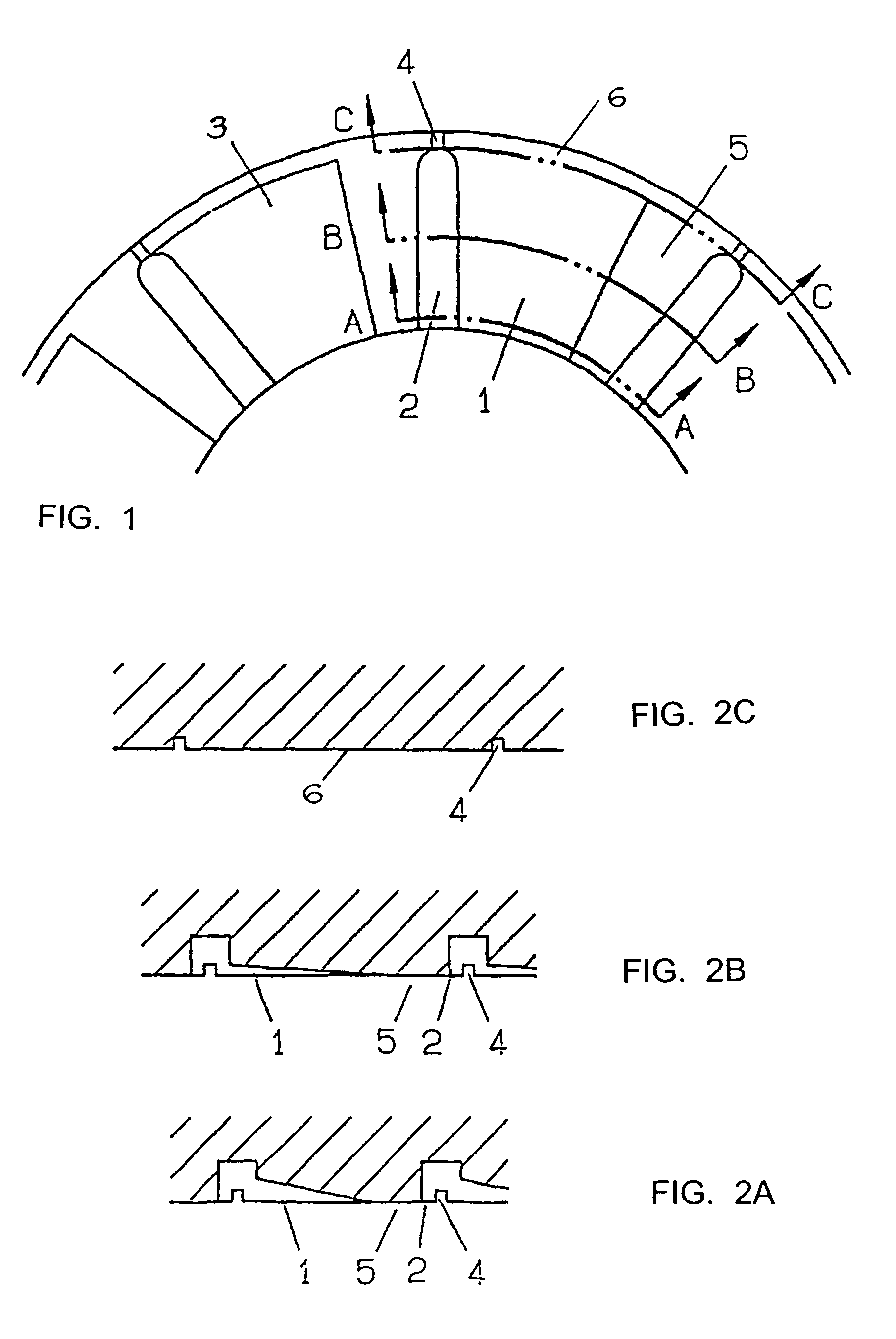
[0029]An axial friction bearing part has a bearing surface 3 in the form of a profiled annular surface, which has several lubricating oil grooves 2 distributed at regular intervals around the circumference of the annular surface, proceeding radially across that surface. Between each pair of lubricating oil grooves is a wedge surface 1 and an adjacent flat trap surface 5.

[0030]The lubricating oil grooves 2 are open at the ...


PUM


Abstract

An axial thrust bearing for axially supporting a rotating shaft of an exhaust gas turbocharger connected to a lubricating oil circuit includes a profiled annular bearing surface which contacts an essentially flat sliding surface, the bearing surface having a plurality of radially extending grooves which are open on the outside circumference, a plurality of coplanar flat trap surfaces located between respective pairs of adjacent grooves, and a plurality of wedge surfaces located between adjacent pairs of respective grooves. Each wedge surface forms a lubricating oil gap which narrows circumferentially toward an adjacent flat trap surface and which narrows radially toward the outside circumference.

Description

PRIORITY CLAIM[0001]This is a U.S. national stage of application No. PCT / EP2003 / 007207, filed on 5 Jul. 2003.BACKGROUND OF THE INVENTION[0002]1. Field of the Invention[0003]The invention pertains to an axial friction bearing for supporting the rotating shaft of an exhaust gas turbocharger connected to a lubricating oil circuit.[0004]2. Description of the Related Art[0005]Hydrodynamic axial thrust bearings are used in many cases to support exhaust gas turbochargers, that is, as plain bearings for the rotating shafts to absorb axial forces and to provide guidance in the axial direction.[0006]Especially in the case of axial-flow turbochargers, the flow conditions produce high axial thrust, which is usually transmitted to the housing by a hydrodynamic axial thrust bearing provided with profiled bearing surfaces.[0007]For example, U.S. Pat No. 6,024,495 discloses an axial friction bearing of this type which includes a bearing body, permanently connected to a bearing housing; a bearing co...

Claims


Application Information

Patent Timeline
Patent Type & Authority Patents(United States)
IPC IPC(8): F16C17/04F01D25/16F02C6/12F16C33/10
CPCF01D25/168F02C6/12F16C17/04F16C33/1065F16C33/1075F16C2360/24F16C17/047
Inventor LINK, HERMANNWERDECKER, FERDINAND
Owner MAN ENERGY SOLUTIONS SA
Why Eureka
Try Eureka