Isolated DC-DC converters with high current capability

a converter and high current technology, applied in the direction of electric variable regulation, process and machine control, instruments, etc., can solve the problems of high current and thermal stress of high current applications, bulky inductor size and hence inflexibility of pcb layout designs, and inability to forward rectifier the way it is not suitable for high current applications, etc., to achieve simplified magnetic design, good thermal management, and low copper loss

Active Publication Date: 2008-12-30
UNIV OF CENT FLORIDA RES FOUND INC
View PDF22 Cites 134 Cited by
  • Summary
  • Abstract
  • Description
  • Claims
  • Application Information

AI Technical Summary

Benefits of technology

[0011]A third objective of the invention is to provide new methods, systems, apparatus and devices for a current tripler secondary-side rectification that has good thermal management, simplified magnetic design and low copper loss for inductor and transformer due to the fact that the load current is better distributed in three inductors.
[0012]A forth objective...

Problems solved by technology

There is one output filter inductor, which carries full load current, leading to high current and thermal stresses for high current applications.
Another problem with the prior art forward rectifier is that full load dc current bias is difficult for the inductor magnetic design and always results in bulky inductor size and hence inflexibility for PCB layout designs.
As a result, the forward rectification is not suitable for high current applications.
Therefore, the filter inductor suffers high current and thermal stresses for high current app...

Method used


Image

  • Isolated DC-DC converters with high current capability
  • Isolated DC-DC converters with high current capability
  • Isolated DC-DC converters with high current capability

Examples


Embodiment Construction

[0039]Before explaining the disclosed embodiments of the present invention in detail it is to be understood that the invention is not limited in its application to the details of the particular arrangements shown since the invention is capable of other embodiments. Also, the terminology used herein is for the purpose of description and not of limitation.

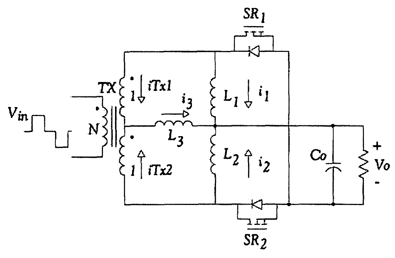
[0040]The method, system, apparatus and device of the present invention provides a current tripler rectification (CTR) topology and the key steady-state operation waveforms are shown in FIGS. 4a and 4b, respectively. There are three output filter inductors L1, L2 and L3 and the transformer Tx secondary side is center-tapped. The primary ac voltage pulse can be generated by state-of-the-art topologies such as push-pull, half bridge and full bridge primary-side topologies. The transformer turns ratio is n: 1:1 as labeled.

[0041]Ignoring the leakage inductance and applying ac voltage pulse to the primary side of the transformer Tx as sho...


PUM


Abstract

A DC-to-DC converter having a transformer with a primary and a tapped secondary, two serial output filter inductors connected parallel with the secondary, a center output filter inductor connected between the secondary tap and serial output inductors, two serially connected switches connected in parallel with the two output inductors for receiving a signal to control operation of the switches during steady state and an output load connected between the serial connection of the serial output inductors and serial switching devices. The transformer primary side connected with double-ended primary-side topologies. The transformer secondary and output filers configured to form a current tripler rectifier, current quadtupler rectifier or current N-tuper rectifier. The output filter inductors evenly share output current resulting in reduction of current and thermal stress during high current application and the rectification topology has simple driving for synchronous rectifier application without increasing complexity of control and operation of primary-side topologies.

Description

[0001]This application claims the benefit of priority to U.S. Provisional Patent Application No. 60 / 808,612 filed on May 26, 2006.FIELD OF THE INVENTION[0002]This invention relates to DC-to-DC converters and, in particular, to methods, systems, apparatus and devices for high-density, high-frequency, and high efficiency isolated dc-dc converters.BACKGROUND AND PRIOR ART[0003]There are three conventional rectifier topologies for low voltage applications. FIG. 1a shows the prior art forward rectifier with its main switching waveforms for steady-state operation. As shown by the waveforms in FIG. 1b, the rectifier transformer has unidirectional utilization. There is one output filter inductor, which carries full load current, leading to high current and thermal stresses for high current applications. Another problem with the prior art forward rectifier is that full load dc current bias is difficult for the inductor magnetic design and always results in bulky inductor size and hence infle...

Claims


Application Information

Patent Timeline
IPC IPC(8): H02M3/335H02M5/42
CPCH02M3/33592Y02B70/1475Y02B70/10
Inventor BATARSEH, ISSAYAO, LIANGBIN
Owner UNIV OF CENT FLORIDA RES FOUND INC
Why Eureka
Try Eureka