
Encryption circuit achieving higher operation speed

Inactive Publication Date: 2008-12-30
RENESAS ELECTRONICS CORP
View PDF25 Cites 0 Cited by
  • Summary
  • Abstract
  • Description
  • Claims
  • Application Information

AI Technical Summary

Benefits of technology

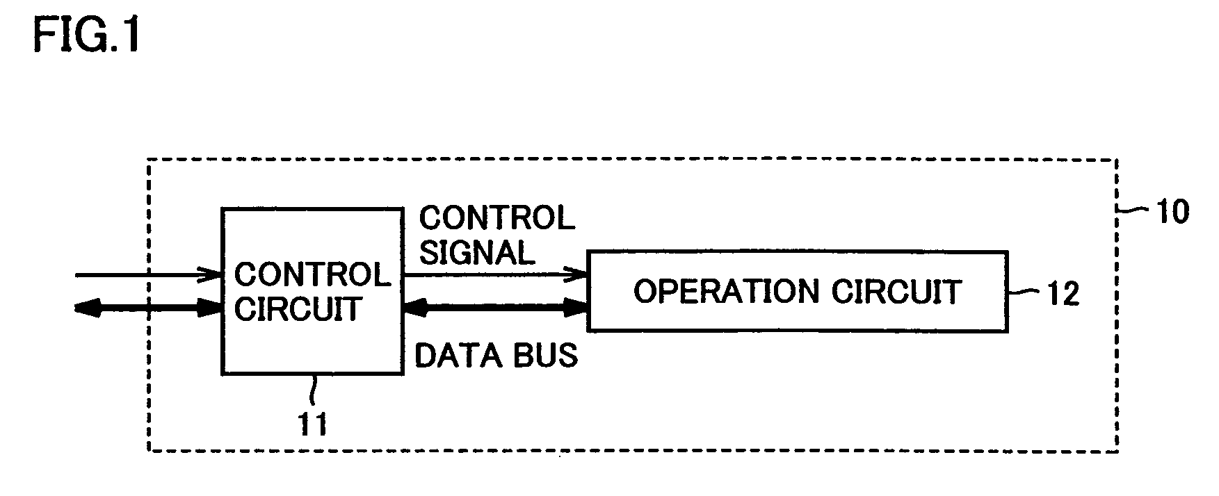
[0011]An object of the present invention is to provide an encryption circuit of which operation clock frequency can be raised and of which operation speed can be improved.
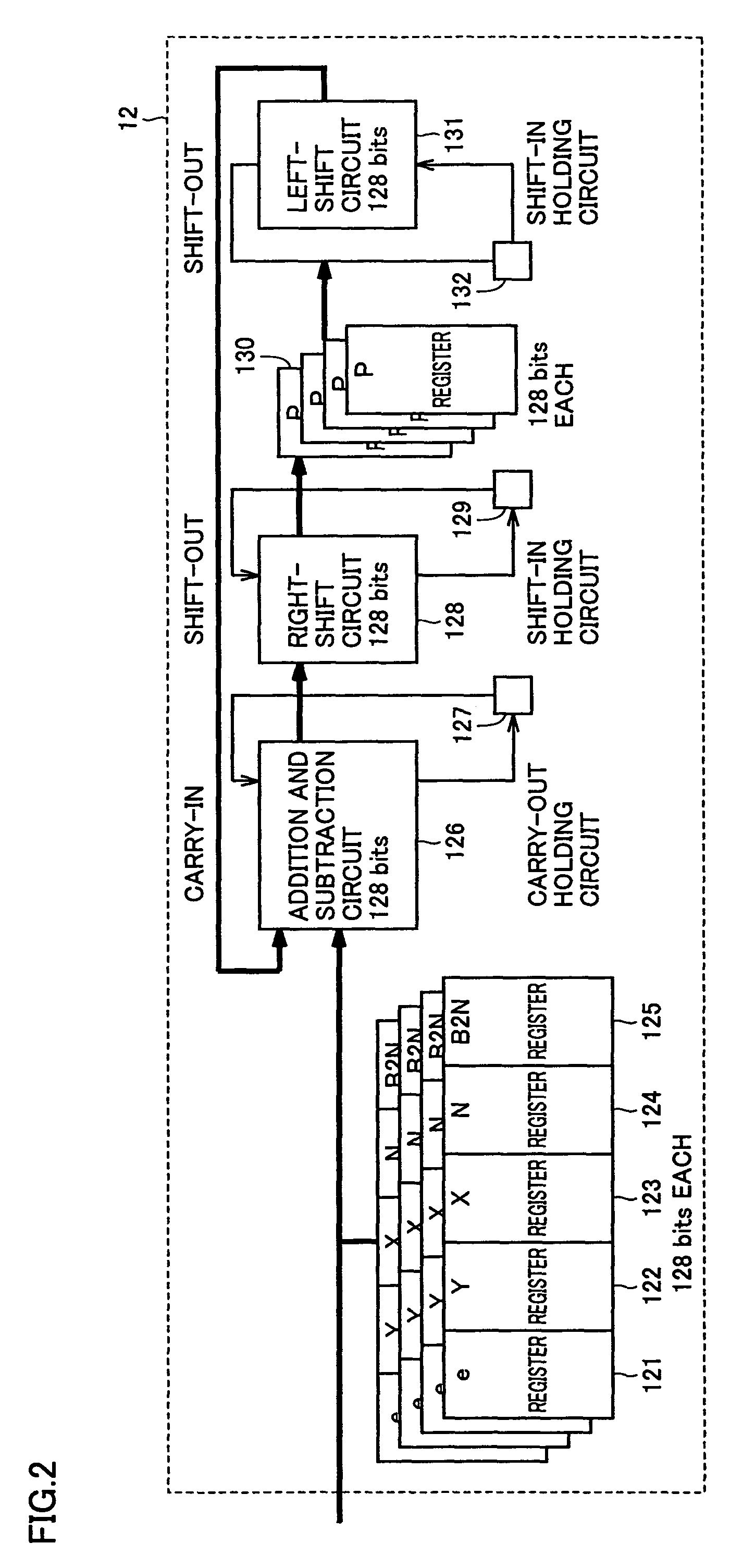
[0013]The addition and subtraction circuit in the first operation circuit performs addition and subtraction using the carry-in signal from the second operation circuit, and outputs the carry-out signal generated through addition and subtraction to the third operation circuit. Therefore, even if a data length of the operation data is extended, the propagation path for the carry can be shortened, and the operation clock frequency of the encryption circuit can be improved.

Problems solved by technology

Security of most cryptosystems in present days is based on difficulty in finding a private key through calculation, considering time required therefor.
The simplest method is to modify the encryption circuit by increasing registers, however, this is not desirable.
In addition, if the bit length which an addition and subtraction circuit can handle at a time is extended, for example, from 128 bits to 256 bits, a propagation path for a carry in addition and subtraction will be extended, leading to difficulty in raising an operation frequency.

Method used


Image

  • Encryption circuit achieving higher operation speed
  • Encryption circuit achieving higher operation speed
  • Encryption circuit achieving higher operation speed

Examples


first embodiment

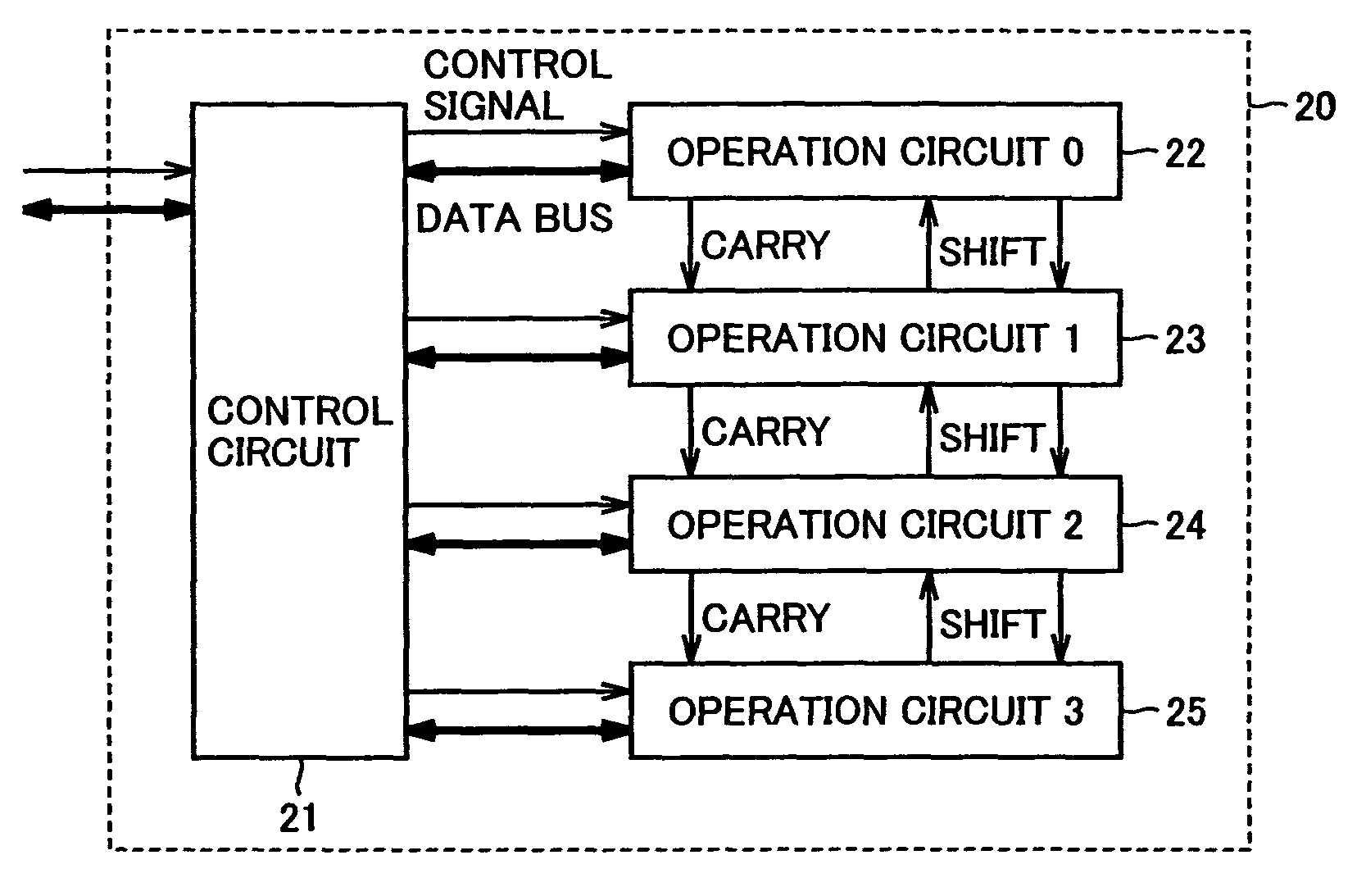
[0031]FIG. 3 is a block diagram showing an overall configuration of an encryption circuit in the first embodiment of the present invention. An encryption circuit 20 includes a control circuit 21 providing overall control of encryption circuit 20, and four operation circuits 0 to 3 (22 to 25). In the present embodiment, RSA scheme is assumed as an encryption scheme, and in addition, operation length of 512 bits is assumed. The present embodiment, however, is not limited to such an example.

[0032]Control circuit 21 outputs data, which is received from outside and is necessary for operation, to operation circuits 0 to 3 (22 to 25) via a data bus, and outputs an operation result received from operation circuits 0 to 3 (22 to 25) via the data bus to the outside. In addition, control circuit 21 outputs a control signal to operation circuits 0 to 3 (22 to 25) in accordance with RSA encryption or decryption algorithm.

[0033]FIG. 4 is a block diagram illustrating an internal configuration of o...

second embodiment

[0044]FIG. 7 is a block diagram showing an overall configuration of an encryption circuit in the second embodiment of the present invention. The encryption circuit in the present embodiment is different from that in the first embodiment shown in FIG. 3 in that the carry-out signal and the left-shift-out signal output from operation circuit 3 are input to operation circuit 0, the right-shift-out signal output from operation circuit 0 is input to operation circuit 3, and the carry-out signal and the shift-out signals form a loop through the operation circuits. Therefore, detailed description for redundant configuration and function will not be repeated. Note that, in the present embodiment, RSA scheme is assumed as the encryption scheme, and an operation length of 1024 bits is assumed. The present embodiment, however, is not limited to such an example.

[0045]FIG. 8 is a block diagram illustrating an internal configuration of operation circuits 0 to 3 (41 to 44) in the second embodiment...

third embodiment

[0051]An encryption circuit in the third embodiment of the present invention is different from that in the second embodiment shown in FIG. 7 only in that operation circuits 0 to 3 have different configuration and function. Therefore, detailed description for redundant configuration and function will not be repeated.

[0052]FIG. 9 is a block diagram illustrating an internal configuration of an operation circuit in the third embodiment. Compared to the internal configuration of the operation circuit in the second embodiment shown in FIG. 8, the operation circuit of the present embodiment is different only in that a B2N0 register 55 and a B2N1 register 65 for calculating in advance fixed data for storage, which is to be used repetitively during the operation, before the operation by the operation circuit, are added. Therefore, detailed description for redundant configuration and function will not be repeated.

[0053]For details of the operation algorithm using B2N0 register 55 and B2N1 reg...


PUM


Abstract

An addition and subtraction circuit performs addition and subtraction using a carry-in signal from another operation circuit, and outputs a carry-out signal generated through addition and subtraction to another operation circuit. A right-shift circuit performs right-shift using a shift-in signal from another operation circuit, and outputs a shift-out signal generated through right-shift to another operation circuit. Therefore, even if a data length of operation data is extended, a propagation path for a carry can be shortened, and an operation clock frequency of an encryption circuit can be increased.

Description

BACKGROUND OF THE INVENTION[0001]1. Field of the Invention[0002]The present invention relates to a technique for encrypting and decrypting information to be used, and more particularly to an encryption circuit encrypting and decrypting data with an operation such as power remainder operation, Montgomery operation, addition and subtraction, or the like.[0003]2. Description of the Background Art[0004]As an information technology develops, an emphasis has been placed on ensuring security on a information network (prevention of theft or destruction of data). Accordingly, techniques for encrypting and decrypting information have been adopted in many cases. The technique is applied not only to a field of information and communication technology, but also to more familiar fields such as transportation, finance, medical care, distribution, and the like. With respect to the technique for encryption and decryption of this type, it is demanded that security of high level can be implemented wit...

Claims


Application Information

Patent Timeline
IPC IPC(8): H04K1/00G06F5/01G06F7/72G09C1/00
CPCG06F7/72G06F5/01G06F7/723
Inventor MIYAUCHI, SHIGENORIYAMAGUCHI, ATSUO
Owner RENESAS ELECTRONICS CORP
Learn More