Method and apparatus for use in encrypted communication

Active Publication Date: 2008-12-30
CORNING INC
View PDF10 Cites 9 Cited by
  • Summary
  • Abstract
  • Description
  • Claims
  • Application Information

AI Technical Summary

Benefits of technology

[0016]A significant advantage of the invention is that the interferometers in the receiver are passive in the sense they do not need to contain active phase modulators driven by random number generators; quantum cryptography receivers are typically required to randomly and dynamically switch between two measurement phase shifts, for example 0° and 180°, that are characteristic of two non-orthogonal phase coding representations used in the system. In contrast, in operation of the present invention, one interferometer can be set to continuously detect one coding representation (e.g. phase shift of 0°) and the other interferometer to continuously detect the other coding representation (e.g. phase shift of 180°). In this way an active receiver design is replaced by a totally passive receiver design thereby reducing complexity and cost.
[0017]Hitherto such passive detection schemes used in quantum cryptography were based upon the ‘random routing’ of quantum signals incident on a 50:50 beam-splitter. The present inventors have realised however that dim depolarised optical pulses incident on a polarisation splitter will also exhibit a similar ‘random routing’ effect.
[0018]Pulses are to be considered effectively unpolarised if they have substantially equal components of mutually perpendicular, mutually incoherent linear polarisation, so that the two orthogonally polarised components will be substantially equally populated; they could be obtained from an inherently unpolarised source, but preferably they are derived from a linearly polarised source, for example a pulsed laser, by a “depolariser” that splits light into two substantially equal components, rotates the plane of polarisation of one of the components by 90° and then recombines them. A preferred form of depolariser will be described below

Problems solved by technology

However, the security of these methods cannot be guaranteed in principle: the former relies on the trustworthiness of the courier and the latter upon unproven assumptions concerning the difficulty of factoring large numbers.
The quantum properties of such signals ensure that any attempt at eavesdropping during transit will yield only partial information on the key and will also generate errors that are detectable by the legitimate users of the apparatus, since any photon detected by an eavesdropper is likely either to fail to reach its intended destination or to have been changed by the detection process.
This leads to the requirement for a polarisation maintaining quantum channel since any polarisation changes induced by the channel will increase the error rate in the system and so may make the system insecure or wholly ineffective.
However, the optical polarisation is not maintained in this type of fiber and instead tends to evolve and fluctuate with time.
T

Method used


Image

  • Method and apparatus for use in encrypted communication
  • Method and apparatus for use in encrypted communication
  • Method and apparatus for use in encrypted communication

Examples


Embodiment Construction

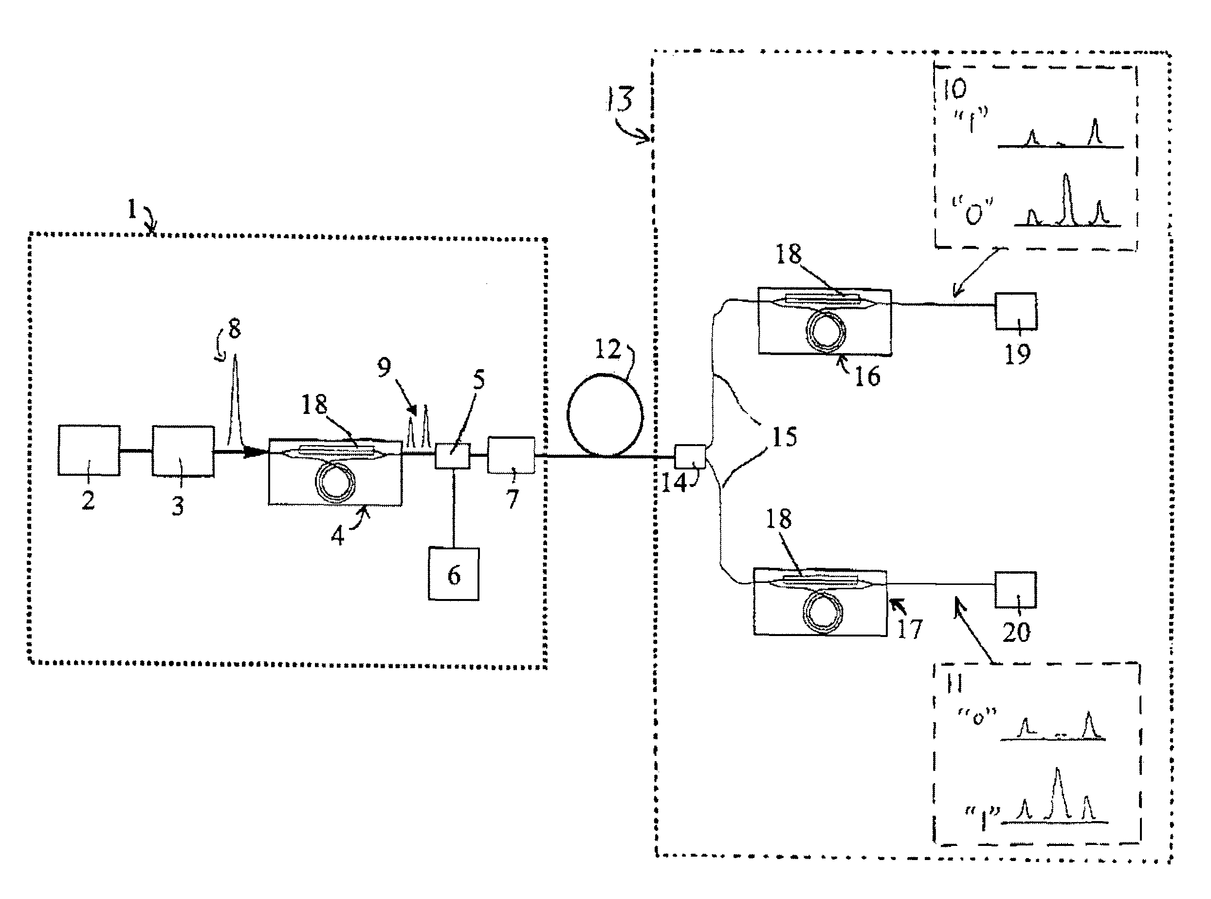
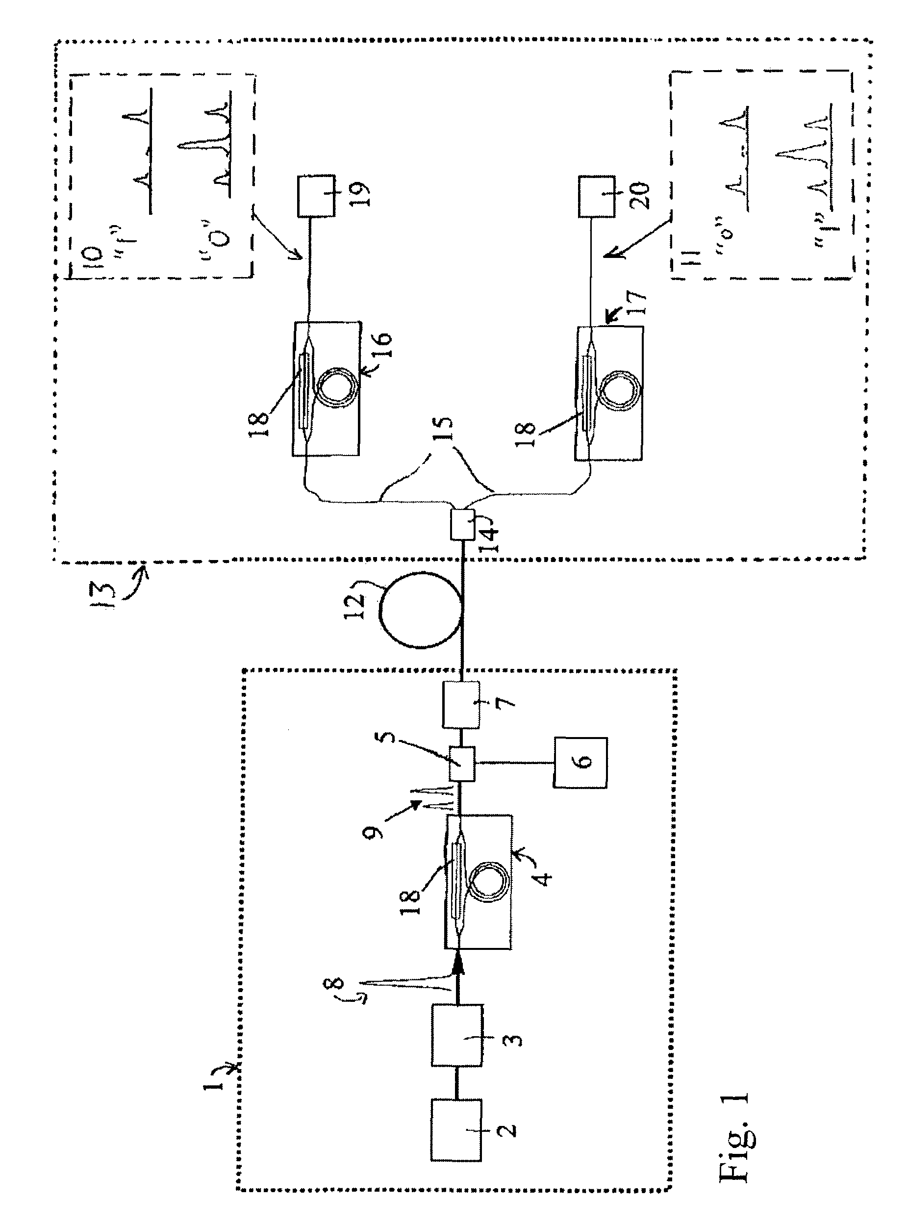
[0029]FIG. 1 depicts the characteristic optical part of an apparatus for establishing a quantum key in accordance with the current invention. The transmitter 1 includes a pulsed semiconductor diode laser 2, an attenuator 3, a waveguide delay stage 4, a phase modulator 5, a random number generator 6 and a depolariser 7. The delay stage shown is based on the waveguide integrated Mach-Zehnder (MZ) interferometers described by Bonfrate et al in the paper referenced above, from which further details may be obtained. The relative (probabilistic) amplitudes and temporal positions of the components of the dim pulses generated by the transmitter are shown at various points in the system 8-11. The random bits that ultimately generate the cryptographic key are encoded in the phase difference of the dim pulse pairs 9 according to the Bennett 1992 protocol referred to above. That is to say the random number generator 6 switches the phase modulator 5 between two phase settings, namely 0° (bit 0) ...


PUM


Abstract

A method and apparatus for secure distribution of cryptographic key information based on quantum cryptography is described. The apparatus incorporates or is used with a transmitter comprising a source of pairs of dim, depolarized light pulses together with a phase modulator and random number generator that are used to encode the pulse pairs with the binary key information by changing the relative phases of the pulses of some pairs. The apparatus incorporates a receiver comprising a polarization beam splitter, and a pair of interferometers and optical detectors. The invention overcomes problems associated with polarization evolution in quantum cryptography systems that incorporate a non-polarization-preserving optical channel (e.g. standard optical fiber). In addition the invention removes the need for an active random number generator and phase modulator at the receiver, because the polarization beam splitter acts as if it were a random router, thereby achieving significant reduction of the cost and complexity of the apparatus.

Description

RELATED APPLICATIONS[0001]This Application claims the benefit of priority under 35 U.S.C. §119 of UK Patent Application No. 0212627.4, filed on May 31, 2002, in the name of Gabriele Bonfrate and Paul D. Townsend, the entire content of which is incorporated herein by reference. This application also claims the benefit of priority under 35 U.S.C. §119(e) of U.S. Provisional Application No. 60 / 424,991 filed on Nov. 8, 2002, the entire content of which is incorporated herein by reference.BACKGROUND TO THE INVENTION[0002]1. Field of the Invention[0003]The present invention relates to a method for use in encrypted communication and to apparatus for use in the method; it is primarily concerned with a technique for establishing cryptographic key information. In particular it relates to a technique known as quantum cryptography.[0004]2. Technical Background[0005]In quantum cryptography fundamental physical laws are exploited to guarantee the secrecy of cryptographic keys transmitted over com...

Claims


Application Information

Patent Timeline
IPC IPC(8): H04K1/00H04L9/08
CPCH04L9/0858
Inventor BONFRATE, GABRIELETOWNSEND, PAUL D.
Owner CORNING INC
Why Eureka
Try Eureka