Magnetic transducer having electrodes with metal and a layer of a salt of that metal

a technology of electromagnetic transducers and electrodes, which is applied in the direction of electromagnetic flowmeters, instruments, measurement devices, etc., can solve the problems of cumbersome and expensive interface with electronics required for remote meter reading, and the nature of the electrodes used to measure electrical potential, so as to reduce noise and electrical characteristics, increase the active area, and minimise the offset potential

Active Publication Date: 2009-01-06
SENTIC LTD
View PDF5 Cites 11 Cited by
  • Summary
  • Abstract
  • Description
  • Claims
  • Application Information

AI Technical Summary

Benefits of technology

[0012]The invention is based on the recognition that by using an electrode having lower noise energy at low frequencies than the electrodes conventionally used in water meters, the frequency of the alternating magnetic field can be reduced for the same signal to noise ratio which in turn reduces the power consumption of the transducer.
[0020]The low-power advantages of the above invention are further enhanced by the reduction in power consumption obtained when the magnetic field is generated by means exhibiting magnetic remenance as discussed above. The invention also comprises a flow meter incorporating such a magnetic transducer, where the low power consumption of the transducer also makes feasible the use of battery power (shown at 110 in FIG. 1) and the advantages in terms of ease of installation that this brings.

Problems solved by technology

To interface this to the electronics required for remote meter reading can be cumbersome and expensive, even when the odometer is replaced by a solid state register having digital counters.
One such limitation is imposed by the nature of the electrodes used to measure the electrical potential difference in the fluid.
This is seldom observed in practical systems, and it is much more likely that an electrical potential difference will be present across the interface.
A static field (DC) measurement will therefore be subject to large instantaneous errors.

Method used


Image

  • Magnetic transducer having electrodes with metal and a layer of a salt of that metal
  • Magnetic transducer having electrodes with metal and a layer of a salt of that metal
  • Magnetic transducer having electrodes with metal and a layer of a salt of that metal

Examples


Embodiment Construction

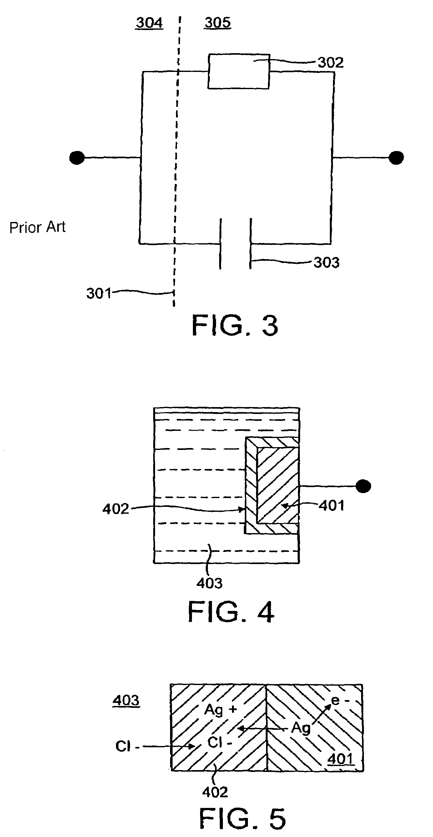
[0033]FIG. 4 shows an electrode of a first embodiment of the invention and comprising a metal element 401 (e.g. a wire, a plate, or a film completely covering an underlying conductor) coated with an ionic compound 402 of the same metal, which is sparingly soluble in the fluid of the flow to be measured 403.

[0034]In the example shown, the metal 401 is silver, with the accompanying compound 402 being silver chloride. FIG. 5 illustrates the fully-reversible, galvanic exchange of charge between the fluid 403 and the metal 401 by means of silver ions crossing the phase boundary between the solid silver electrode 401 and the hydrated silver chloride layer 402. The electrical potential across the interface is defined by the Nernst equation, which in turn depends on the surface concentration of AgCl and the liquid concentration of Cl ions. While these quantities will not be constant, they may normally be expected to vary on a timescale much greater than the period of the alternating magneti...


PUM


Abstract

A magnetic transducer (109) for measuring the flow of a fluid (108) has electrodes (102) and an alternating magnetic field (107), an electrode (102) having lower noise energy at frequencies below 5 Hz than an electrode comprising carbon or corrosion-resistant metal alloy. The noise characteristic of the electrode (102) at magnetic field frequencies around 1 Hz is lower than that of an electrode comprising carbon or corrosion-resistant metal alloy.

Description

TECHNICAL FIELD[0001]This invention relates to magnetic flow transducers and in particular to magnetic water flow meters.BACKGROUND ART[0002]In a conventional utility water meter, a mechanical flow transducer (typically positive displacement or single / multi-jet turbine) is coupled to a register mechanism that measures the number of repetitive cycles of the transducer. This mechanism is often a mechanical odometer. To interface this to the electronics required for remote meter reading can be cumbersome and expensive, even when the odometer is replaced by a solid state register having digital counters.[0003]Use of a flow transducer that is also solid-state reduces such interface problems. Such a flow transducer is a magnetic flow transducer of a kind that is well known and shown by way of example in the cross-sectional view of FIG. 1.[0004]Flow tube, 101 incorporates a magnetic transducer 109 comprising a pair of electrodes, 102, disposed across a diameter of the pipe 101, with at lea...

Claims


Application Information

Patent Timeline
Patent Type & Authority Patents(United States)
IPC IPC(8): G01F1/58G01F1/60
CPCG01F1/584G01F1/586G01F1/60G01F1/58
Inventor KNILL, ALEXANDER CHARLESGLAUSER, ANTHONY ROBERT
Owner SENTIC LTD
Why Eureka
Try Eureka