
Catalyst-coated membrane, membrane-electrode assembly, and polymer electrolyte fuel cell

a technology of membrane electrolyte and catalyst, which is applied in the direction of fuel cell details, cell components, electrochemical generators, etc., can solve the problems that the durability and cycle life characteristics of the membrane-electrolyte assembly cannot be sufficiently improved, and the degradation of the membrane-electrolyte assembly and the catalyst-coated membrane cannot be sufficiently prevented when the fuel cell is operated for a long period of time. , to achieve the effect of improving the durability of the catalys

Inactive Publication Date: 2009-01-06
PANASONIC CORP
View PDF16 Cites 5 Cited by
  • Summary
  • Abstract
  • Description
  • Claims
  • Application Information

AI Technical Summary

Benefits of technology

[0022]In order to achieve the above objects, the present inventors conducted extensive studies on the possibility that the anode catalyst layer and the cathode catalyst layer closely attached to the polymer electrolyte membrane may greatly affect the durability of the polymer electrolyte membrane, and they successfully improved the durability of the catalyst-coated membrane and the membrane-electrode assembly by designing a catalyst layer having the following structure. Thus, the present invention has been accomplished.

Problems solved by technology

The above-listed prior art publications, however, are essentially intended to improve the initial cell characteristics of the fuel cells and the mechanical strength and heat resistance of the polymer electrolyte membranes, and therefore no sufficient investigation has been made on a membrane-electrode assembly and a catalyst-coated membrane in the case of using the fuel cell for a long period of time, or on the improvement of durability and cycle life characteristics of the fuel cells.
To be more specific, even if the durability of a polymer electrolyte membrane is reinforced based on the techniques according to the above patent documents 1 and 2, the degradation of the membrane-electrolyte assembly as well as that of the catalyst-coated membrane cannot be sufficiently prevented when the fuel cell is operated for a long period of time.

Method used

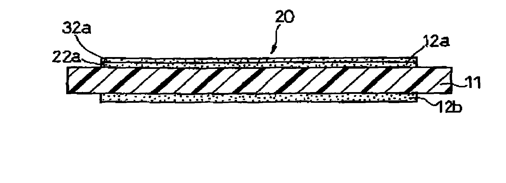
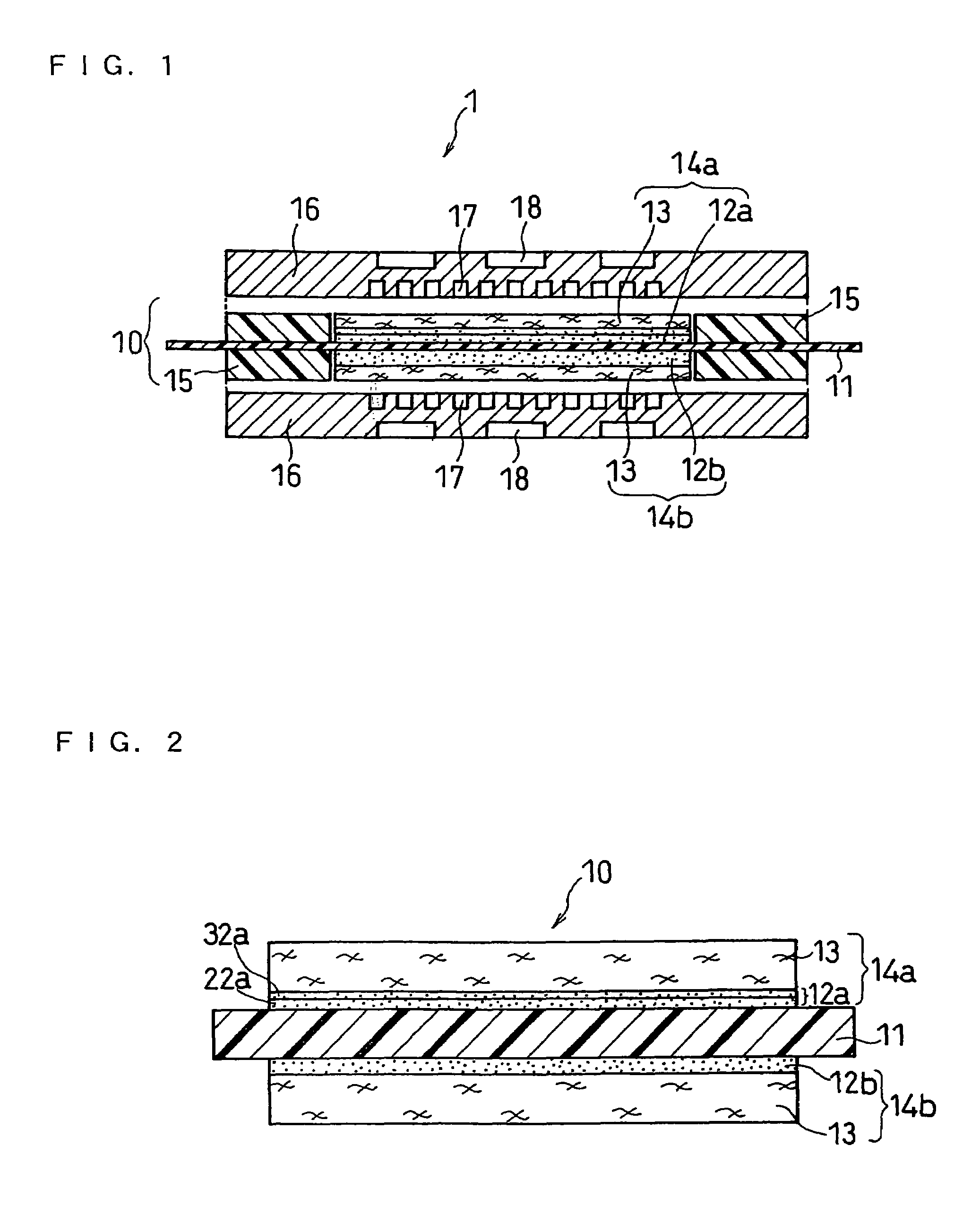
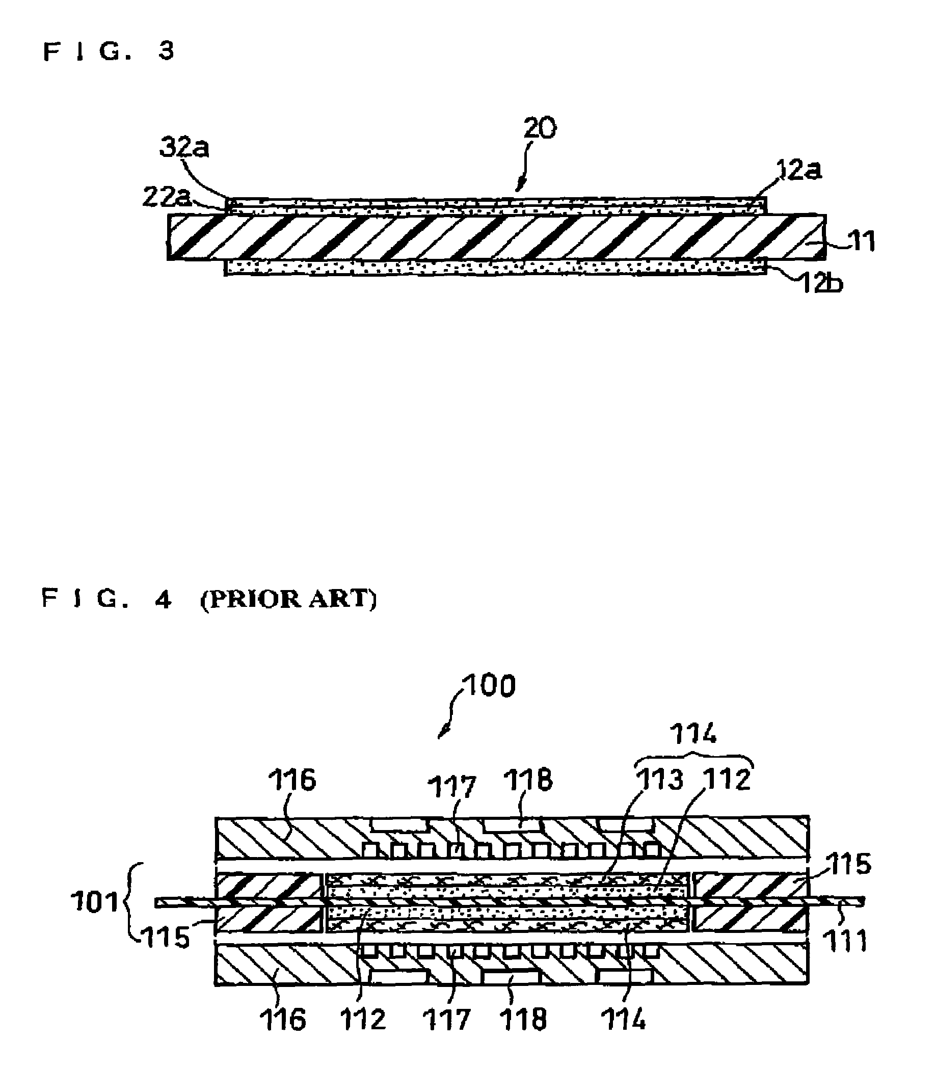

Image

  • Catalyst-coated membrane, membrane-electrode assembly, and polymer electrolyte fuel cell
  • Catalyst-coated membrane, membrane-electrode assembly, and polymer electrolyte fuel cell
  • Catalyst-coated membrane, membrane-electrode assembly, and polymer electrolyte fuel cell

Examples


example 1

COMPRATATIVE EXAMPLE 1

[0107]A catalyst-coated membrane, a membrane-electrode assembly and a unit cell were produced in the same manner as in EXAMPLE 1 except that a cathode catalyst layer having a ratio (WP / WCat-C) of 0.4 and a monolayer structure was formed.

example 2

[0108]A catalyst-coated membrane, a membrane-electrode assembly and a unit cell were produced in the same manner as in EXAMPLE 1 except that a cathode catalyst layer including the following three layers (three-layer structure) was formed: a first layer (innermost layer) having a ratio (WP / WCat-C) of 1.0 and containing platinum in an amount of 0.12 mg / cm2 (⅕ of the total amount of the platinum contained; a second layer (intermediate layer) having a ratio (WP / WCat-C) of 0.6 and containing platinum in an amount of 0.24 mg / cm2 (⅖ of the total amount of the platinum contained); and a third layer (outermost layer) having a ratio (WP / WCat-C) of 0.4 and containing platinum in an amount of 0.24 mg / cm2 (⅖ of the total amount of the platinum contained).

example 3

[0110]A catalyst-coated membrane, a membrane-electrode assembly and a unit cell were produced in the same manner as in EXAMPLE 1 except that the ratio (WP / WCat-C) in the first layer (innermost layer) of the cathode catalyst layer was adjusted to 0.8.


PUM

PropertyMeasurementUnit
electromotive forceaaaaaaaaaa
specific surface areaaaaaaaaaaa

Abstract

An object of the present invention is to provide a catalyst-coated membrane suitable for achieving a polymer electrolyte fuel cell that sufficiently prevents a decrease in the initial characteristics and also exhibits sufficient cell performance for a long period of time and has excellent durability. In at least the cathode catalyst layer, the ratio (WP / WCat-C) of the weight of the polymer electrolyte (WP) to the weight of the catalyst-carrying carbon (WCat-C) is decreased from an innermost layer positioned closest to the polymer electrolyte membrane toward an outermost layer positioned farthest from the polymer electrolyte membrane. The ratio (WP / WCat-C) in the innermost layer is 0.8 to 3.0, and the ratio (WP / WCat-C) in the outermost layer is 0.2 to 0.6.

Description

BACKGROUND OF THE INVENTION[0001]The present invention relates to a catalyst-coated membrane, a membrane-electrode assembly and a polymer electrolyte fuel cell comprising the same.[0002]Since fuel cells (FC) have high power generation efficiency and are environmentally friendly, widespread use thereof as a distributed energy system is expected in the future. Particularly, polymer electrolyte fuel cells that use a polymer electrolyte having cations (hydrogen ions) are expected to be utilized in mobile units such as automobiles, distributed power generation systems and home cogeneration systems because they have high output density, they can operate at low temperatures and they can be made smaller.[0003]Conventional polymer electrolyte fuel cells generate electricity and heat simultaneously by electrochemically reacting a fuel gas containing hydrogen and an oxidant gas containing oxygen such as air. FIG. 4 is a schematic sectional view illustrating a basic structure of a unit cell des...

Claims


Application Information

Patent Timeline
Patent Type & Authority Patents(United States)
IPC IPC(8): H01M4/86H01M4/96H01M4/88H01M4/90H01M4/92H01M8/02H01M8/10
CPCH01M4/8605H01M4/8642H01M4/8657H01M4/881H01M4/8828H01M4/8892H01M4/921H01M4/926H01M8/1004H01M8/102H01M8/1039Y02E60/521Y02E60/50H01M4/86H01M8/02
Inventor YOSHIMURA, MIKIKOHORI, YOSHIHIROTSUJI, YOICHIROYOSHIDA, AKIHIKOYONAMINE, TAKESHIUCHIDA, MAKOTO
Owner PANASONIC CORP
Learn More