Vehicle power supply system

a power supply system and vehicle technology, applied in hybrid vehicles, cell components, instruments, etc., can solve the problems of high battery voltage, large increase in cost, increase in weight, etc., and achieve the effect of improving the torque characteristic of rotating electric machines and being light in weigh

Inactive Publication Date: 2009-02-03
MITSUBISHI ELECTRIC CORP
View PDF20 Cites 19 Cited by
  • Summary
  • Abstract
  • Description
  • Claims
  • Application Information

AI Technical Summary

Benefits of technology

[0009]The present invention has been made to solve the problems as described above, and an object thereof is to provide a vehicle power supply system which can improve a torque characteristic of a rotating electric machine, is light in weight, and is inexpensive.
[0011]By this, it becomes possible to reduce a voltage drop due to the DC wiring line, and it is possible to improve the torque characteristic of the rotating electric machine and to realize the lightweight and inexpensive vehicle power supply system.

Problems solved by technology

In the structure as stated above, there have been problems that a DC wiring line for connecting the battery and the control unit including the inverter becomes long, so that a voltage drop in the DC wiring line becomes large, and in order to obtain both a desired torque and a desired rotation speed in the rotating electric machine, there occurs such a situation eventually that a battery voltage must be made high, and a large increase in cost and an increase in weight are caused.

Method used


Image

  • Vehicle power supply system
  • Vehicle power supply system
  • Vehicle power supply system

Examples


embodiment 1

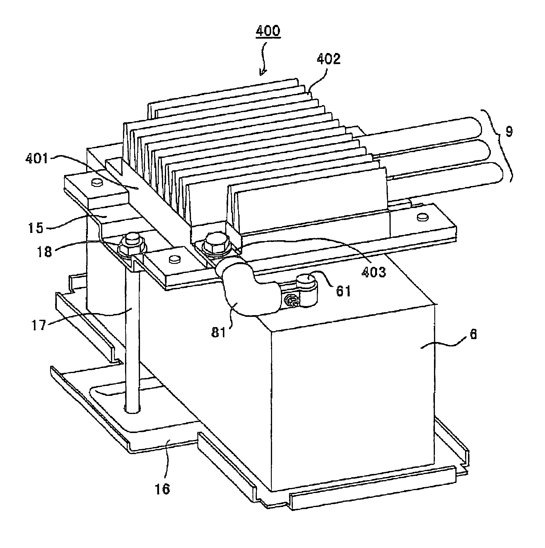
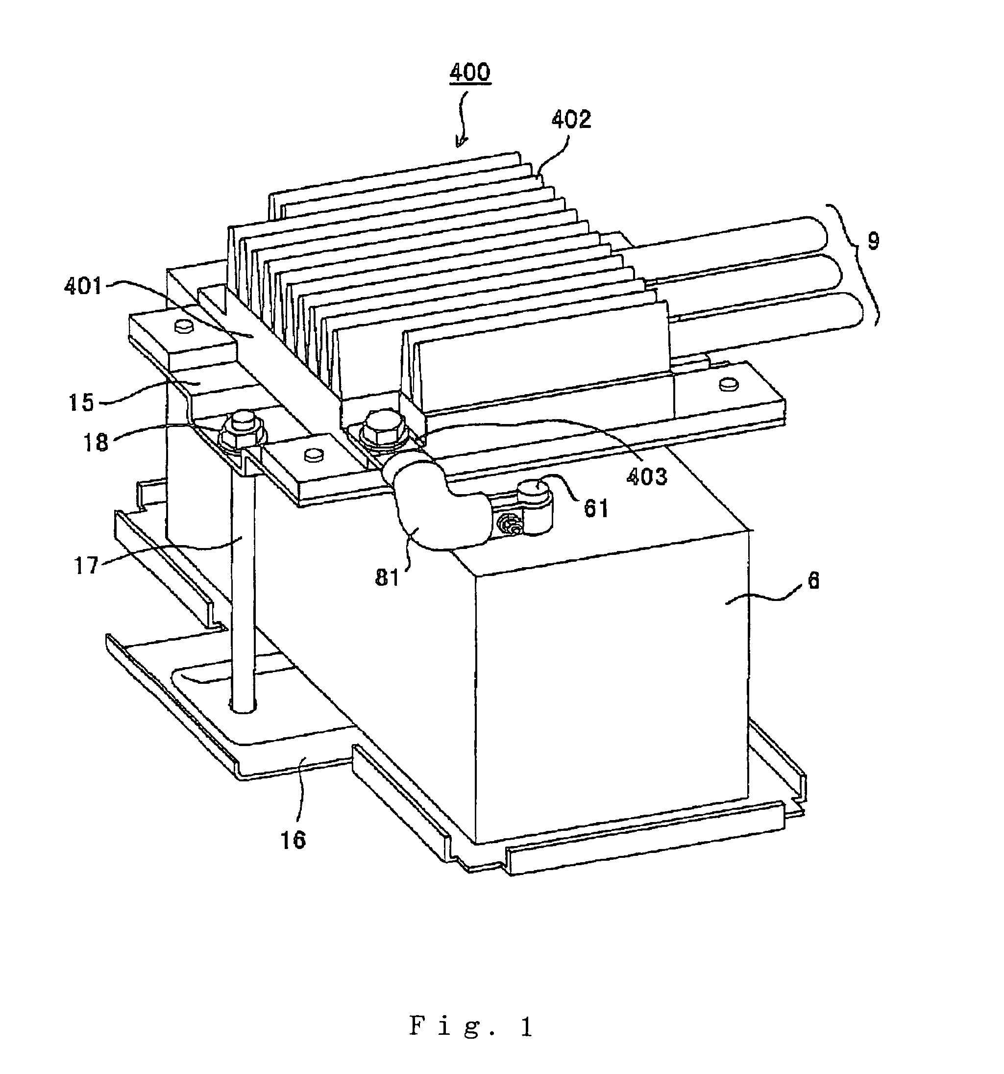
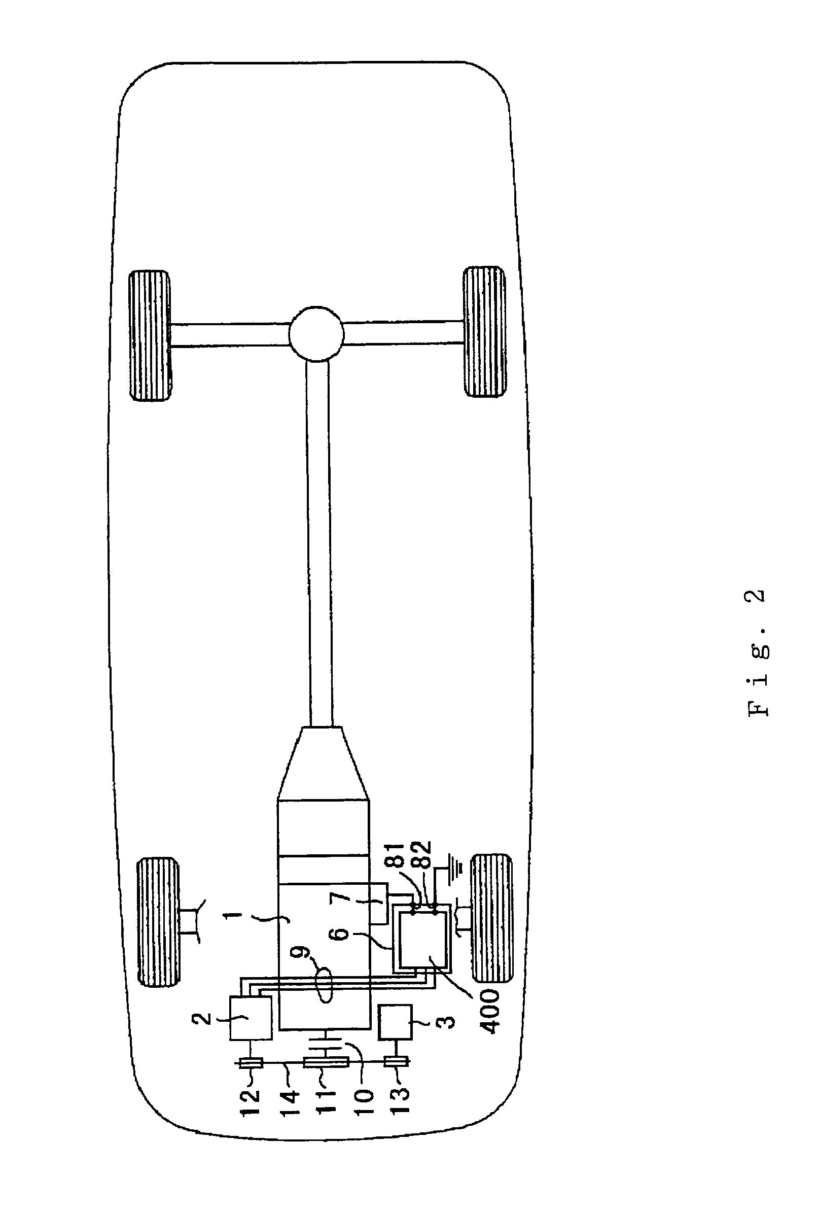
[0022]Embodiment 1 of this invention will be described with reference to FIGS. 1 to 3. FIG. 1 is a perspective view showing a structure in the embodiment 1. FIG. 2 is a conceptual view showing an arrangement relation of the whole of a vehicle in the embodiment 1. FIG. 3 is a curve view showing a torque characteristic of a rotating electric machine in the embodiment 1.

[0023]FIG. 3 shows an example of comparison between a torque characteristic of a rotating electric machine 2 at the time when an attachment structure of an inverter unit of the embodiment 1 of this invention is adopted and a torque characteristic at the time when a 12V battery is used instead of a high voltage battery in a conventional hybrid vehicle, and simultaneously shows a load torque characteristic of an engine in terms of rotation speed of the rotating electric machine, and intersection points with the respective torque characteristics indicate points of cranking rotation speeds at the time of starting.

[0024]In F...

embodiment 2

[0054]Embodiment 2 of this invention will be described with reference to FIG. 4. FIG. 4 is a perspective view showing a structure of the embodiment 2.

[0055]Except for a specific structure described here, the embodiment 2 has the same structure as the structure of the embodiment 1 described before and has the same operation. In the drawing, the same signs denote the same or equivalent portions.

[0056]In FIG. 4, one side end face 16a of a battery tray 16 is high like a wall along a side end face of a 12V battery 6, and an inverter unit 400 is attached to the side end face 16a by a bolt 19 in a vertically placed state.

[0057]The 12V battery 6 is clamped and fixed by a nut 18 through an attachment bolt 17 in such a state that it is held between a battery fixing plate 15 having one L-shaped portion 15a inserted and fixed to a slit-shaped hole 16b provided above the side end face 16a of the battery tray 16 and a bottom of the battery tray 16.

[0058]At this time, since the battery tray 16 is ...

embodiment 3

[0077]Embodiment 3 of this invention will be described with reference to FIG. 5. FIG. 5 is a perspective view showing a structure of the embodiment 3.

[0078]Except for a specific structure described here, the embodiment 3 has the same structure as the structure of the embodiment 1 described before and has the same operation. In the drawing, the same signs denote the same or equivalent portions.

[0079]In FIG. 5, a battery fixing plate 15 is integrally fixed by welding or caulking to an upper side of an attachment plate 401a fixed integrally with an inverter unit main body 401 of an inverter unit 400 and constituting a part of the inverter unit 401, while a not-shown L-shaped pawl is formed at an under side of the attachment plate 401a, and is inserted and fixed to a not-shown slit-shaped hole provided at a side end face 16a of a battery tray 16.

[0080]Then, a 12V battery 6 is clamped and fixed by a nut 18 through an attachment bolt 17 in such a state that it is held between the battery ...


PUM

PropertyMeasurementUnit
voltageaaaaaaaaaa
DC electric poweraaaaaaaaaa
AC electric poweraaaaaaaaaa

Abstract

In a vehicle power supply system including a battery, an inverter unit for converting DC electric power of the battery into AC electric power and supplying it to a rotating electric machine to drive it, an AC wiring line for connecting the rotating electric machine and the inverter unit, and a DC wiring line for connecting the inverter unit and the battery, the inverter unit is placed in a vicinity of the battery so that the DC wiring line becomes shorter than the AC wiring line. By this, a voltage drop due to the DC wiring line is reduced, and a torque characteristic of the rotating electric machine can be improved.

Description

BACKGROUND OF THE INVENTION[0001]1. Field of the Invention[0002]The present invention relates to a vehicle power supply system, and particularly to a positional relation between an inverter unit for controlling a rotating electric machine mounted in an electric vehicle, a hybrid vehicle or the like and a battery, and to a vehicle power supply system which can improve a torque characteristic of the rotating electric machine.[0003]2. Description of the Related Art[0004]Against the backdrop of the prevention of global warming, emission reduction of CO2 has been requested.[0005]The reduction of CO2 in a vehicle means an improvement in fuel consumption performance, and as one of solutions thereto, the development and practical application of an electric vehicle (EV) or a hybrid vehicle (HEV) has been pursued.[0006]Here, especially, functions required for a rotating electric machine mounted in a hybrid vehicle include idling stop at the time of stop of a vehicle, energy regeneration durin...

Claims


Application Information

Patent Timeline
Patent Type & Authority Patents(United States)
IPC IPC(8): B60L1/00G05F3/06B60R16/04B60K1/04B60K6/26B60K6/28B60K6/40B60L9/18B60L50/15B60L50/16B60R16/02B60R16/03H01M10/60H01M10/613H01M10/625H01M10/647H01M10/6554H01M10/6568H01M50/202H01M50/244H01M50/249
CPCB60K1/04B60K6/26B60K6/28B60K6/48B60L3/0046B60L11/1874B60L11/1877B60L11/1879H01M2/1077H01M2/1083H01M10/5004H01M10/5016H01M10/5097B60R16/03H01M10/5057H01M10/5075H01M10/5077H02M7/003Y02T10/6221Y02T10/7005Y02T10/705H01M10/625H01M10/6556H01M10/6568H01M10/6567H01M10/667H01M10/613B60L58/26B60L50/66B60L50/64Y02T10/62Y02T10/70Y02E60/10H01M50/249H01M50/202H01M50/244
Inventor ASAO, YOSHIHITOKITAMURA, YUTAKA
Owner MITSUBISHI ELECTRIC CORP
Why Eureka
Try Eureka