

Compound solar battery and manufacturing method thereof
a solar battery and manufacturing method technology, applied in the field of compound solar batteries and manufacturing methods thereof, can solve the problems of inability to achieve desired electricity production, degraded cell quality of gaas and ingap, and inability to meet cell quality requirements, etc., to achieve the effect of improving the efficiency of conversion to electric energy
- Summary
- Abstract
- Description
- Claims
- Application Information
AI Technical Summary
Benefits of technology
Problems solved by technology
Method used
Image

Examples
first embodiment
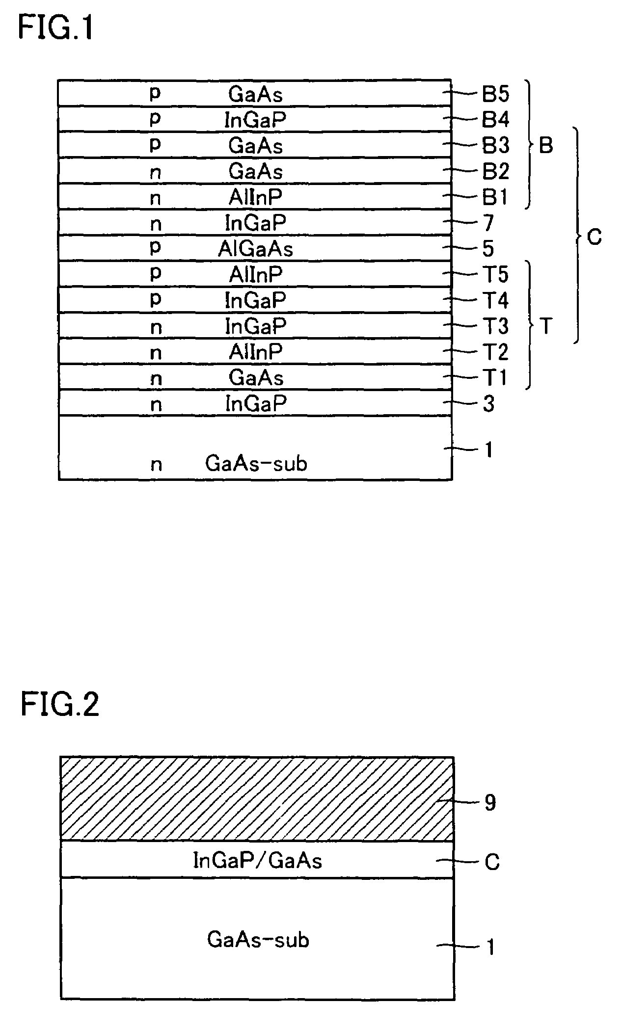
[0086]A compound solar battery in accordance with a first example embodiment will be described. A 2-junction type compound solar battery having a bottom cell and a top cell will be described as an example of the cell body of the compound solar battery.
[0087]First, the manufacturing method will be described. As a substrate, a GaAs substrate (1×1018 cm−3, Si doped, 50 mm in diameter) is prepared. The GaAs substrate is put in a vertical MOCVD (Metal Organic Chemical Vapor Deposition) apparatus.
[0088]Thereafter, as shown in FIG. 1, an n-type InGaP layer 3 having the thickness of about 0.5 μm is formed by epitaxial growth on a surface of GaAs substrate 1. InGaP layer 3 will be an intermediate layer between a cell body that will be formed on InGaP layer 3 and GaAs substrate 1.
[0089]Thereafter, on InGaP layer 3, single crystal layers to be the top cell T are formed by epitaxial growth. Specifically, an n-type GaAs layer T1, an n-type AlInP layer T2, an n-type InGaP layer T3, a p-type InGaP...
second embodiment
[0126]Here, in order to confirm the effect of light confinement attained by the back surface electrode, a compound solar battery having a cell body structure different from the one described above was evaluated as an example. This will be described in the following.
[0127]First, as shown in FIG. 11, in the compound solar battery in accordance with the present embodiment, cell body C is directly formed on the surface of back surface electrode 9. In cell body C, a p-type InGaP layer 21 is formed on back surface electrode 9. On InGaP layer 21, a p-type GaAs layer 22 is formed.
[0128]On GaAs layer 22, an n-type GaAs layer 23 is formed. On GaAs layer 23, an n-type InGaP layer 24 is formed. At a prescribed position on InGaP layer 24, a surface electrode 15 is formed, with a contact of n-type GaAs layer interposed.
[0129]The compound solar battery is formed through the method similar to that of the compound solar battery described above. Specifically, first, layers from n-type GaAs layer 25 t...
third embodiment
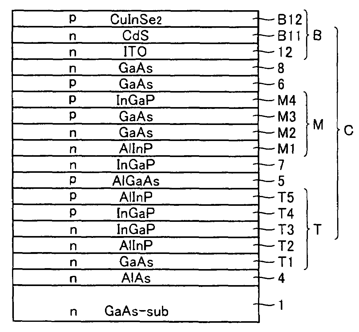
[0136]A compound solar battery in accordance with a third embodiment will be described. Here, by way of example, a 3-junction type compound solar battery having a bottom cell, middle cell and top cell as the cell body of the compound solar battery will be described.
[0137]First, manufacturing method will be described. As a substrate, a GaAs substrate (1×1018 cm−3, Si doped, 50 mm in diameter) is prepared. The GaAs substrate is put in a vertical MOCVD apparatus.
[0138]Then, as shown in FIG. 13, on GaAs substrate 1, an n-type AlAs layer 4 to be the intermediate layer, having the thickness of about 0.5 μm is formed by epitaxial growth.
[0139]On AlAs layer 4, layers to be the top cell T are formed by epitaxial growth. Specifically, an n-type GaAs layer T1, an n-type AlInP layer T2, an n-type InGaP layer T3, a p-type InGaP layer T4 and a p-type AlInP layer T5 are formed successively.
[0140]Thereafter, as a tunnel junction, on AlInP layer 5, a p-type AlGaAs layer 5 and n-type InGaP layer 7 ar...
PUM
 Abstract
Description
Claims
Application Information