Exhaust emission purifying apparatus for engine

a technology for purifying apparatus and exhaust, which is applied in the direction of mechanical apparatus, engine components, machines/engines, etc., can solve the problems of nox not being satisfactorily reduced and eliminated, urea accumulation forms an obstruction to the flow of exhaust emission in the exhaust pipe, and the elimination rate of nox might decrease in some cases, so as to enhance the elimination rate of nox

Inactive Publication Date: 2009-03-10
NISSAN DIESEL MOTOR CO
View PDF19 Cites 4 Cited by
  • Summary
  • Abstract
  • Description
  • Claims
  • Application Information

AI Technical Summary

Benefits of technology

[0008]Therefore, in view of such problems, it is an object of the present invention to provide an exhaust emission purifying apparatus for an engine with which deposition of a reducing agent in an exhaust passage is suppressed even if an exhaust temperature from an engine remains low thereby enhancing an elimination rate of NOx and which can detect accumulation of a constituent of the reducing agent due to the deposition of the constituent in the exhaust passage.

Problems solved by technology

In this case, the urea water is reduced by an amount corresponding to the precipitated urea, the urea water injection-supplied from the injection nozzle is not effectively used for the catalytic reduction reaction, there is a possibility that NOx cannot satisfactorily be reduced and eliminated, and an elimination rate of NOx might decrease in some cases.
Moreover, when only moisture evaporates from the urea water injection-supplied into the exhaust emission on the upstream side of the reduction catalyst and urea is precipitated and accumulates in the exhaust pipe in the vicinity of the injection nozzle, the accumulated urea forms obstruction against flowing of the exhaust emission in the exhaust pipe.
Therefore, there might be possibility of increase in exhaust pressure and decrease of mileage.

Method used


Image

  • Exhaust emission purifying apparatus for engine
  • Exhaust emission purifying apparatus for engine
  • Exhaust emission purifying apparatus for engine

Examples


first embodiment

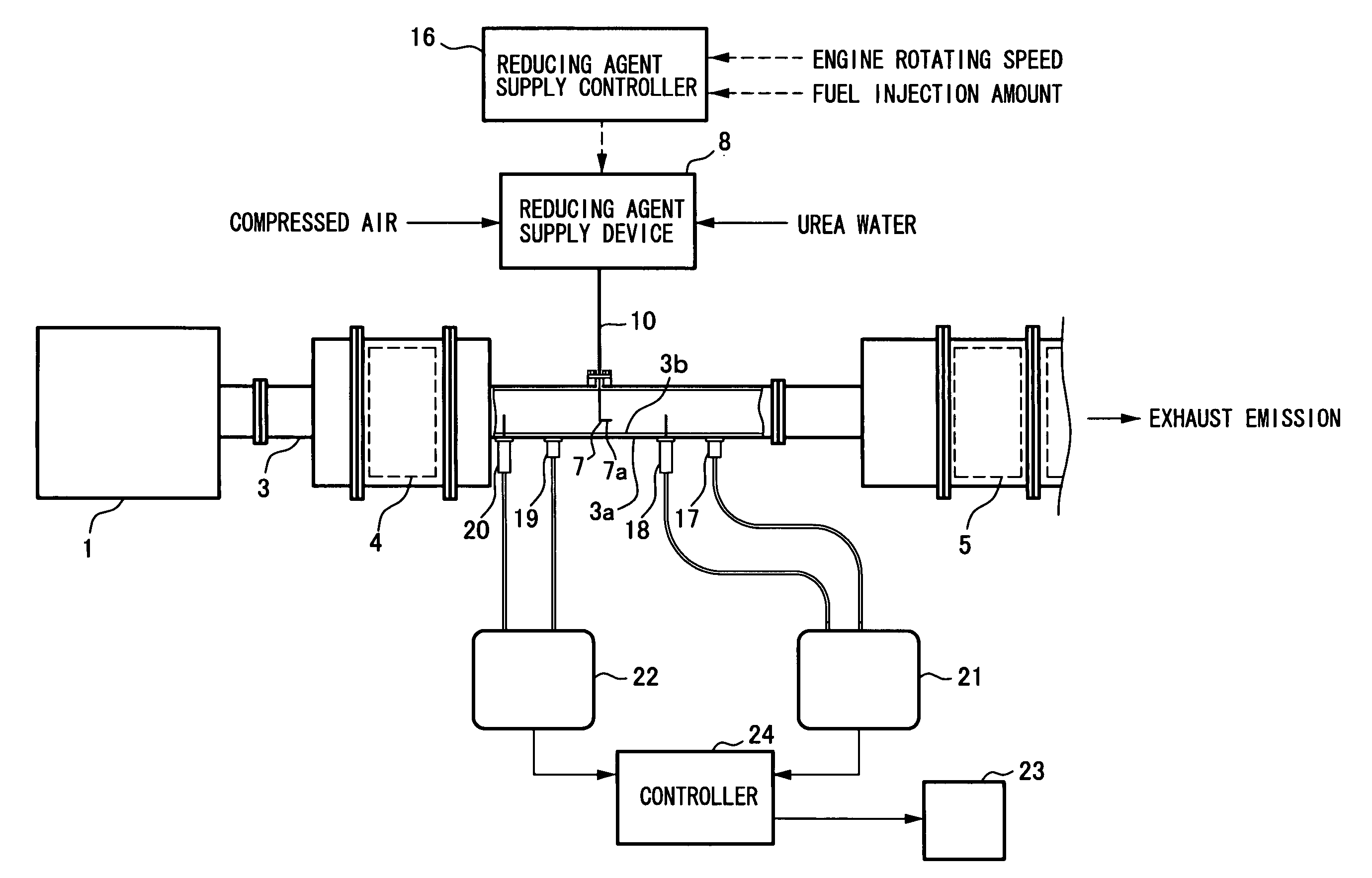
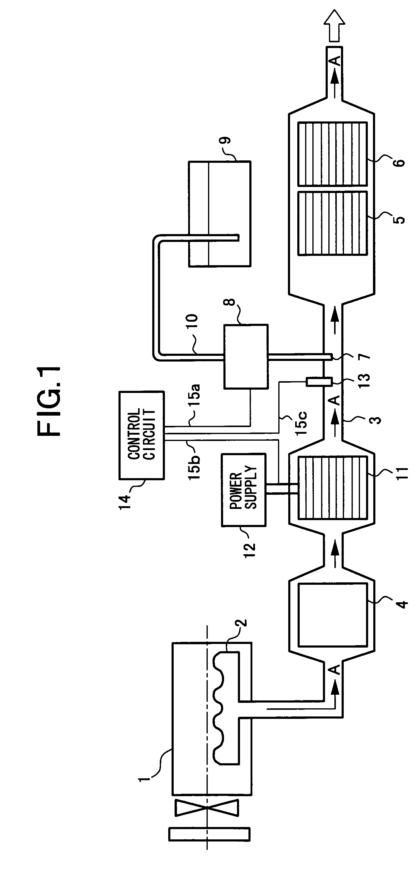
[0041]FIG. 1 shows a structure of an exhaust emission purifying apparatus for an engine according to the invention. This exhaust emission purifying apparatus reduces and eliminates NOx emitted from a diesel engine, a gasoline engine, or the like mounted on a mobile vehicle by using a reducing agent. The exhaust emission of the engine 1 using gasoline or diesel oil as fuel is emitted into the air from an exhaust pipe 3 as an exhaust passage through an exhaust manifold 2. Specifically, in the exhaust pipe 3, a nitrogen monoxide (NO) oxidation catalyst 4, a NOx reduction catalyst 5, and an ammonia slip oxidation catalyst 6 are disposed in order from an exhaust emission upstream side, and a temperature sensor, a NOx sensor and the like are disposed in front and at the rear of the catalysts to thereby form an exhaust system. However, details are not illustrated.

[0042]The oxidation catalyst 4 reduces NO and the like contained in the exhaust emission passing through the exhaust pipe 3 by o...

second embodiment

[0065]Here, in FIG. 5, a control procedure performed by the controller 24 of the exhaust emission purifying apparatus will be described. First, the controller 24 starts the control when power is supplied by turning on a power supply switch such as a key switch. The control according to the illustrated flow chart is repeatedly performed every predetermined time.

[0066]First, at step 1 (referred to as “S1” in the drawings and hereinafter the same shall apply), the outer wall temperatures T1, T3 and the exhaust emission temperatures T2, T4 are input from the first through fourth temperature sensors 17 through 20.

[0067]At step S2, the first subtracter 21 subtracts the outer wall temperature T1 from the exhaust emission temperature T2 to obtain a temperature difference ΔTd. The processing at steps S1 and S2 using first temperature sensor 17 and the second temperature sensor 18 corresponds to a first temperature deference detecting means.

[0068]At step S3, the second subtracter 22 subtract...


PUM


Abstract

In order to suppress deposition of constituent of a reducing agent (dissolved matter) in an exhaust passage of an engine enhancing an elimination rate of NOx even when temperature of an exhaust emission from the engine is low, an exhaust emission purifying apparatus is provided with an electro-generative-heat carrier provided on an upstream side of an injection nozzle that supplies the reducing agent into the exhaust emission on upstream side of a reduction catalyst in an exhaust pipe, the exhaust emission being heated to a temperature equal to or higher than a melting point of the dissolved matter whereby deposition of the dissolved matter on an inner wall surface of the exhaust pipe is suppressed to effectively use the supplied reducing agent for catalytic reduction reaction, even when the exhaust emission temperature is lower than the melting point of the dissolved matter of the reducing agent.

Description

[0001]This application is a continuation of PCT / JP2004 / 012746, filed on Sep. 2, 2004.BACKGROUND OF THE INVENTION[0002]1. Field of the Invention[0003]The present invention relates to an exhaust emission purifying apparatus for an engine for reducing and eliminating nitrogen oxides (NOx) which is emitted from a diesel engine, a gasoline engine, or the like mounted on a mobile vehicle, by supplying a reducing agent into an exhaust emission on an upstream side of a reduction catalyst, and particularly, relates to an exhaust emission purifying apparatus for an engine for suppressing deposition of a constituent of the reducing agent (solute of the reducing agent) in an exhaust passage to enhance an elimination rate of NOx even if an exhaust temperature from the engine is low and for detecting deposition and accumulation of the constituent of the reducing agent in the exhaust passage.[0004]2. Description of the Related Art[0005]As a system for eliminating especially NOx out of particulate ...

Claims


Application Information

Patent Timeline
Patent Type & Authority Patents(United States)
IPC IPC(8): F01N3/00F01N3/20F01N9/00F01N13/00
CPCF01N3/103F01N3/2013F01N3/2066F01N3/208F01N11/00F01N11/002F01N13/0097F01N13/0093F01N13/009F01N2470/18F01N2550/05F01N2560/06F01N2560/08F01N2560/14F01N2610/02F01N2610/10F01N2900/08Y02T10/26Y02T10/47Y02T10/24Y02T10/12Y02T10/40
Inventor MASUDA, KOUJIHIRATA, KIMINOBUMASAKI, NOBUHIKO
Owner NISSAN DIESEL MOTOR CO
Why Eureka
Try Eureka