
Exhaust emission purifying apparatus for engine

a technology of exhaust gas purification apparatus and purification apparatus, which is applied in the direction of lighting and heating apparatus, combustion types, separation processes, etc., can solve the problems of engine power degradation, engine power degradation or fuel consumption degradation, and achieve the effect of easy washing of the detached injection nozzle, easy washing and easy washing

Inactive Publication Date: 2009-03-10
NISSAN DIESEL MOTOR CO
View PDF78 Cites 31 Cited by
  • Summary
  • Abstract
  • Description
  • Claims
  • Application Information

AI Technical Summary

Benefits of technology

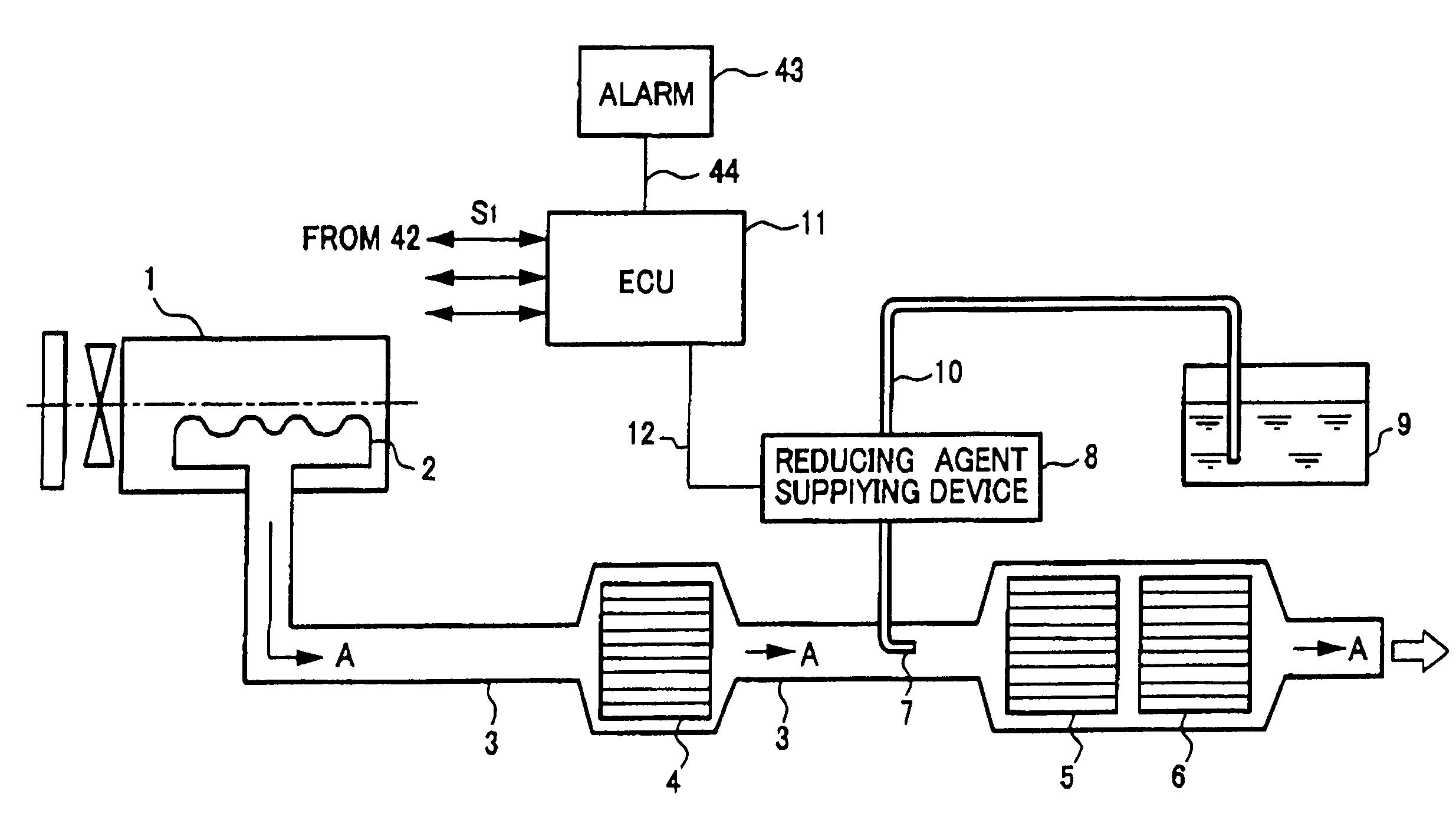
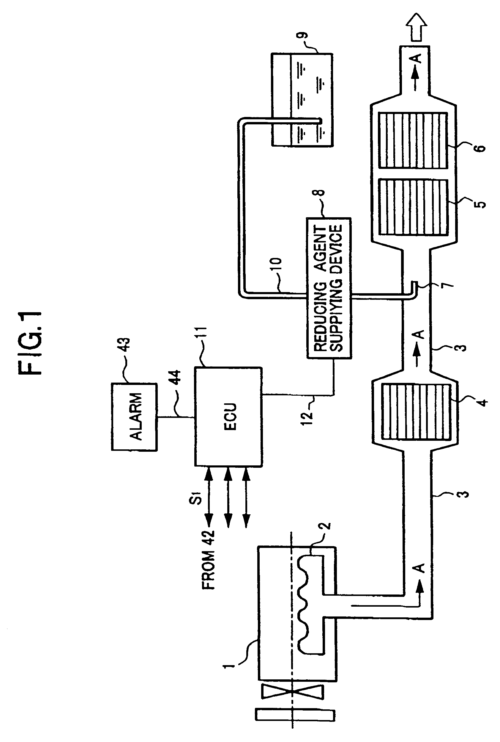
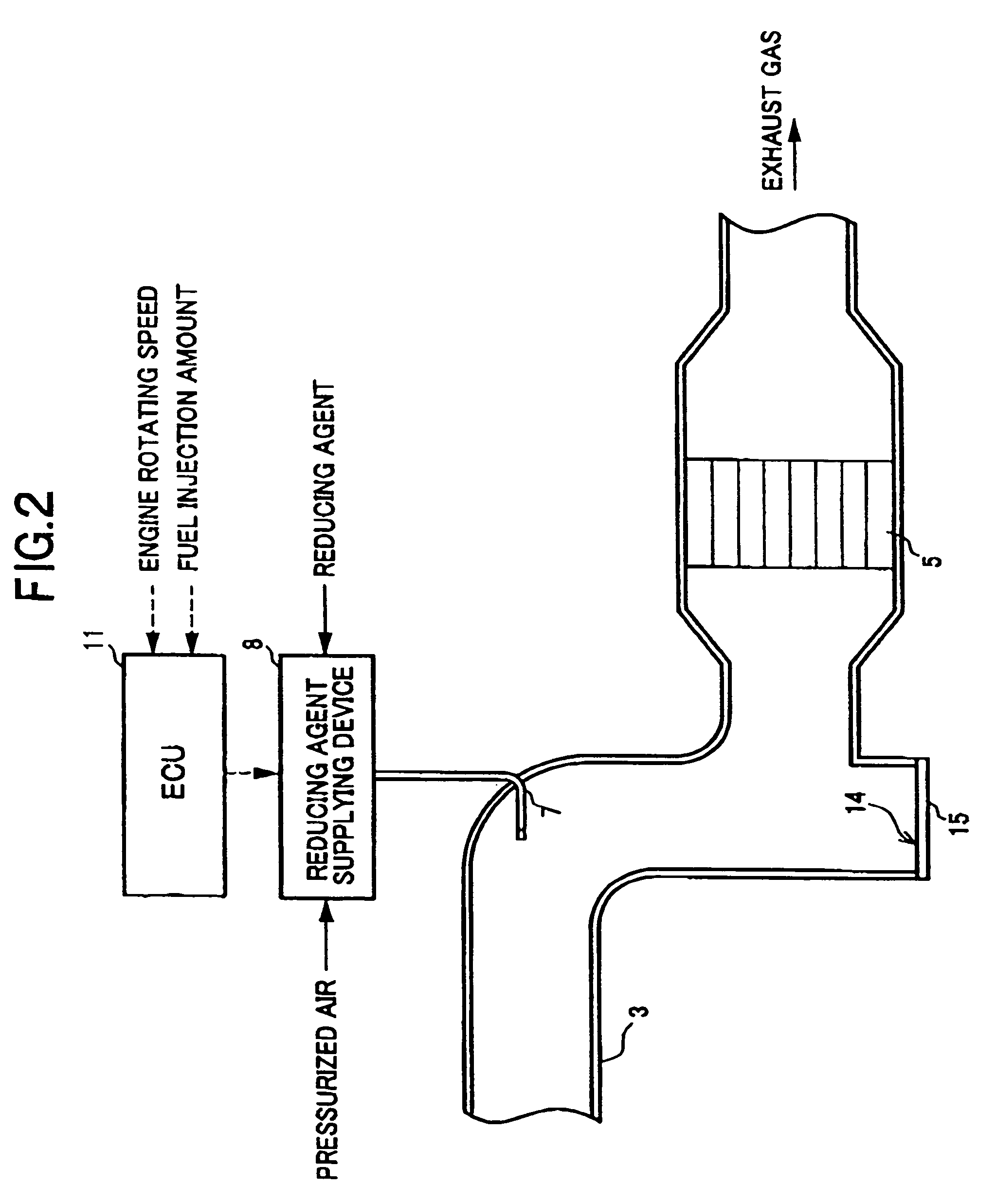
"The present invention provides an exhaust emission purifying apparatus for an engine that can remove the reducing agent component that is deposited in the exhaust system. The apparatus includes a reduction catalytic converter, an injection nozzle, and a reducing agent supply device. A recess portion is formed on the inner wall of the lower portion of the exhaust passage, which is detachably assembled. The recess portion has a bottom wall that can be heated up to the fusion point or above of the reducing agent. A thermal insulating material is disposed on the outer face of the heater to suppress heat radiation. The invention also provides a blocking means for blocking the passage portion between the portion to which the reducing agent is attached and another portion on which the reduction catalytic converter is disposed. The blocking means can be disposed on the positions of the exhaust upstream side and downstream side with the injection nozzle therebetween. The invention aims to improve the purification efficiency of the exhaust emission from the engine."

Problems solved by technology

In such a case, there is a possibility that the exhaust emission pressure of the engine rises resulting in a degradation of engine power or in a degradation of fuel consumption.
Further, also in the case where light oil or gasoline being a fuel, or alcohol, is used as the reducing agent, similarly to the above, a component such as carbon or the like may be deposited in the exhaust passage, resulting in a possibility of the degradation of engine power or the degradation of fuel consumption.
However, in the conventional technology, it has been difficult to readily accomplish the removal.

Method used


Image

  • Exhaust emission purifying apparatus for engine
  • Exhaust emission purifying apparatus for engine
  • Exhaust emission purifying apparatus for engine

Examples


second embodiment

[0101]FIG. 10 is an explanatory view showing a main part of the structure in which the reducing agent (urea water) attached portion in the exhaust pipe 3 is constructed to be detachable as required. In this embodiment, as the portion to which the urea water is attached, a nozzle downstream side portion 36 of the exhaust pipe 3, which extends by the predetermined length from the vicinity of the exhaust downstream side of the injection nozzle, may be dismounted from the assembled condition. As a result, when it is considered that the urea water is attached to the vicinity of the exhaust downstream side of the injection nozzle 7 in the exhaust pipe 3, it is possible to dismount the nozzle downstream side portion 36 in the arrow “B” direction. Then, it is possible to wash the detached nozzle downstream side portion 36 with the water or the like, to remove deposited urea on the inner wall or the like of the exhaust pipe 3.

[0102]Thereafter, the detached and washed nozzle downstream side p...

third embodiment

[0103]FIG. 11 is an explanatory and diagrammatic view showing a main part of the structure in which the reducing agent (urea water) attached portion in the exhaust pipe 3 is constructed to be detachable. In this embodiment, as the portion to which the urea water is attached, a nozzle downstream side portion 38 of the exhaust pipe 3, which extends from the vicinity of the exhaust downstream side of the injection nozzle 7 to the vicinity 37 of an inlet portion of the reduction catalytic converter 5, may be detached as required. As a result, when it is considered that the urea water impinges upon the vicinity 37 of the inlet portion of the reduction catalytic converter 5 on the exhaust downstream side of the injection nozzle 7 in the exhaust pipe 3, to be attached to the portion to which the urea water is susceptible to be attached, it is possible to detach the nozzle downstream side portion 38 in the arrow “B” direction. Then, it is possible to wash the detached nozzle downstream side...

fourth embodiment

[0105]FIG. 12 is an explanatory and diagrammatic view showing a main part of the structure in which the reducing agent (urea water) attached portion in the exhaust pipe 3 is constructed to be detachable as required. In this embodiment, as the portion to which the urea water is attached, a nozzle front and rear portion 39 of the exhaust pipe 3, which extends by the predetermined length on the exhaust downstream side from the vicinity of the exhaust downstream side of the injection nozzle 7, is detachably mounted. As a result, when it is considered that the urea water is attached to the injection nozzle 7 and also to the vicinity of the exhaust downstream side of the injection nozzle 7 in the exhaust pipe 3, it is possible to detach the nozzle front and rear portion 39 in the arrow “B” direction. Then, it is possible to wash the detached nozzle front and rear portion 39 with the water or the like, to remove urea deposited on the inner wall or the like of the exhaust pipe 3.

[0106]There...


PUM

PropertyMeasurementUnit
temperatureaaaaaaaaaa
widthaaaaaaaaaa
thermal insulatingaaaaaaaaaa

Abstract

An exhaust emission purifying apparatus for an engine having: a reduction catalytic converter disposed in an exhaust system of the engine, for reductively purifying nitrogen oxides in the exhaust emission with a reducing agent; an injection nozzle for injection-supplying the reducing agent to an exhaust upstream side of the reduction catalytic converter in an exhaust pipe of the exhaust system; and a reducing agent supply device supplying the reducing agent to the injection nozzle, in which a recess portion is formed on an inner wall on a lower portion of the exhaust pipe, by concaving a site to which at least the reducing agent injection-supplied from the injection nozzle is attached, and also, a bottom wall of the recess portion is made detachable.

Description

[0001]This application is a continuation of PCT / JP2005 / 001531, filed on Feb. 2, 2005.BACKGROUND OF THE INVENTION[0002]1. Field of the Invention[0003]The present invention relates to an exhaust emission purifying apparatus adapted for Use in purifying exhaust emission from a diesel engine, a gasoline engine or the like, mounted on an on-moving vehicle by supplying a reducing agent to the flow of exhaust emission on an upstream side of a reduction catalytic converter in an exhaust passage of the engine, to thereby reductively eliminate nitrogen oxides (NOx) emitted from the engine. More particularly, it relates to an exhaust emission purifying apparatus for an engine capable of removing a component of a reducing agent, which is deposited in an exhaust passage as a result that the supplied reducing agent is attached to or deposited on the inside of the exhaust passage[0004]2. Description of the Related Art[0005]Several types of exhaust emission purifying apparatuses has been proposed r...

Claims


Application Information

Patent Timeline
Patent Type & Authority Patents(United States)
IPC IPC(8): F01N3/00B01D53/94F01N3/08F01N3/20F01N3/24F01N3/28F01N13/02
CPCB01D53/9431F01N3/005F01N3/2066F01N13/18F01N13/0097F01N13/009B01D2251/2062F01N2240/20F01N2260/14F01N2260/20F01N2450/30F01N2470/00F01N2560/08F01N2570/14F01N2610/02F01N2610/03Y02T10/24Y02A50/20Y02T10/12
Inventor HIRATA, KIMINOBUMASAKI, NOBUHIKOMIYATA, TATSUJI
Owner NISSAN DIESEL MOTOR CO
Learn More