
High throughput continuous pulsed laser deposition process

a laser deposition and high throughput technology, applied in the direction of superconductor devices, vacuum evaporation coating, coatings, etc., can solve the problems of pushed to the limit of performance by older urban electric power systems in particular, and lengths of coated conductor wire samples have been fabricated

Inactive Publication Date: 2009-03-10
SUPERPOWER INC
View PDF23 Cites 21 Cited by
  • Summary
  • Abstract
  • Description
  • Claims
  • Application Information

AI Technical Summary

Benefits of technology

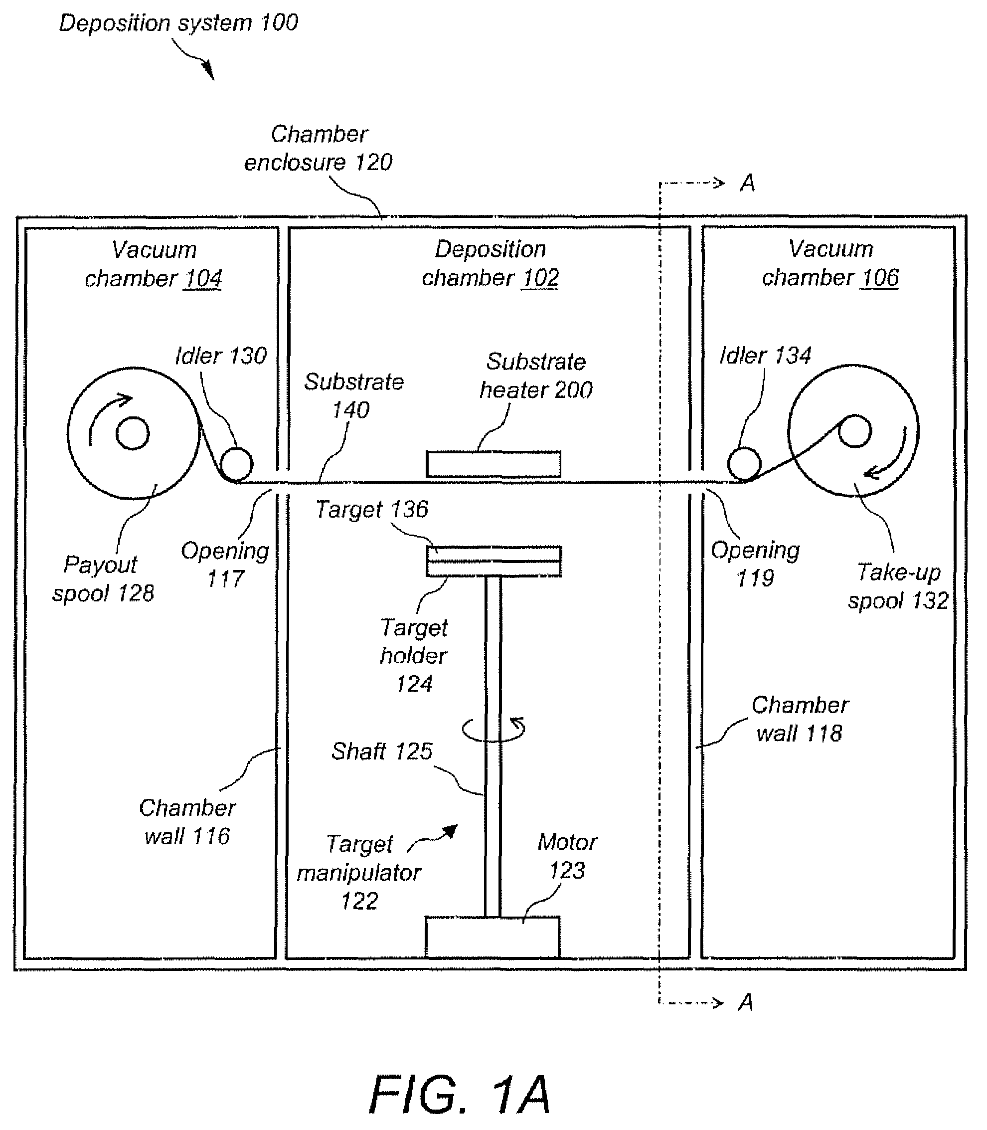
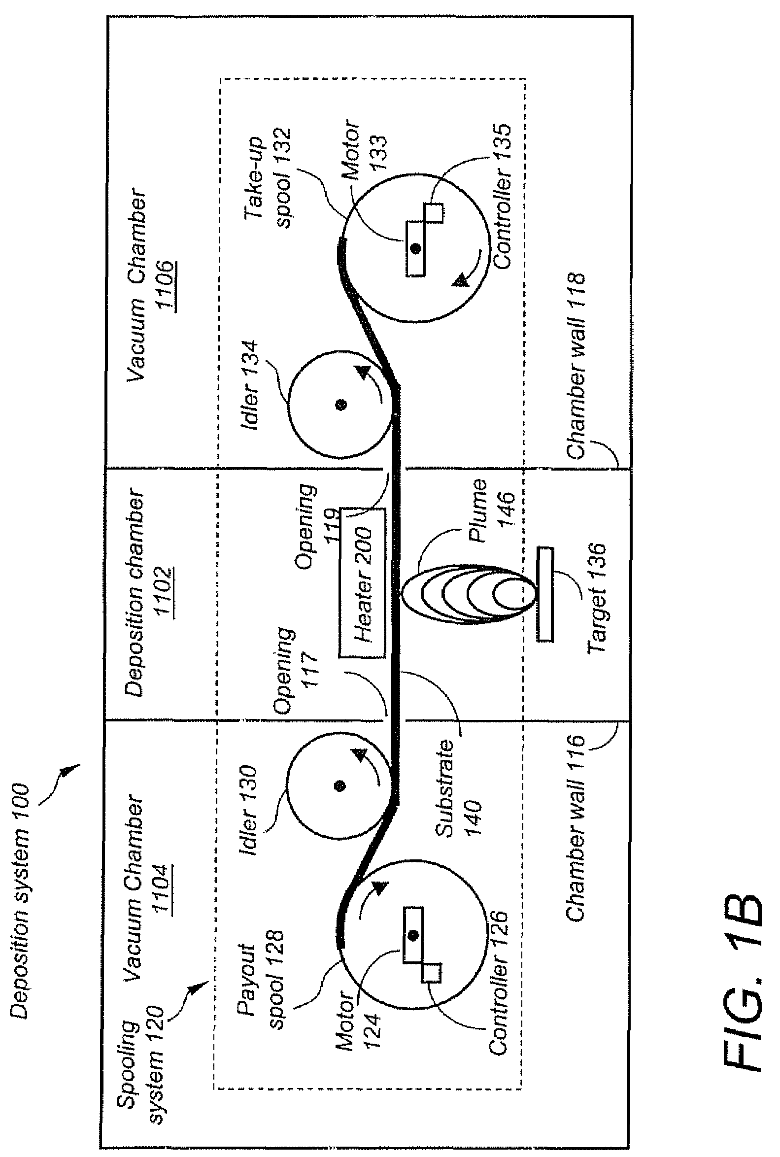
[0037]The presence of multiple overlapping plumes arranged sequentially effectively lengthens the deposition zone wherein the substrate is exposed to the evaporant material. The thickness of the HTS film deposited onto the substrate tape is controlled by the rotational speed of a payout and take-up spool within the spooling system, thereby controlling the time that the substrate is present in the deposition zone.
[0039]Subsequent to undergoing the deposition of a superconducting layer, the tape is made to wind onto a take-up spool such that the HTS-coated side winds in an orientation toward the center of the spool rather than toward the outer perimeter of the spool, as the superconducting film is less likely to be damaged when under compressive strain rather than when under tensile strain. As an additional protective measure, a length of polymer interleaf may be wound into the take-up spool between tape layers as the tape winds onto the take-up spool, thereby protecting the superconducting layer form being scratched by the non-coated side of the substrate tape.
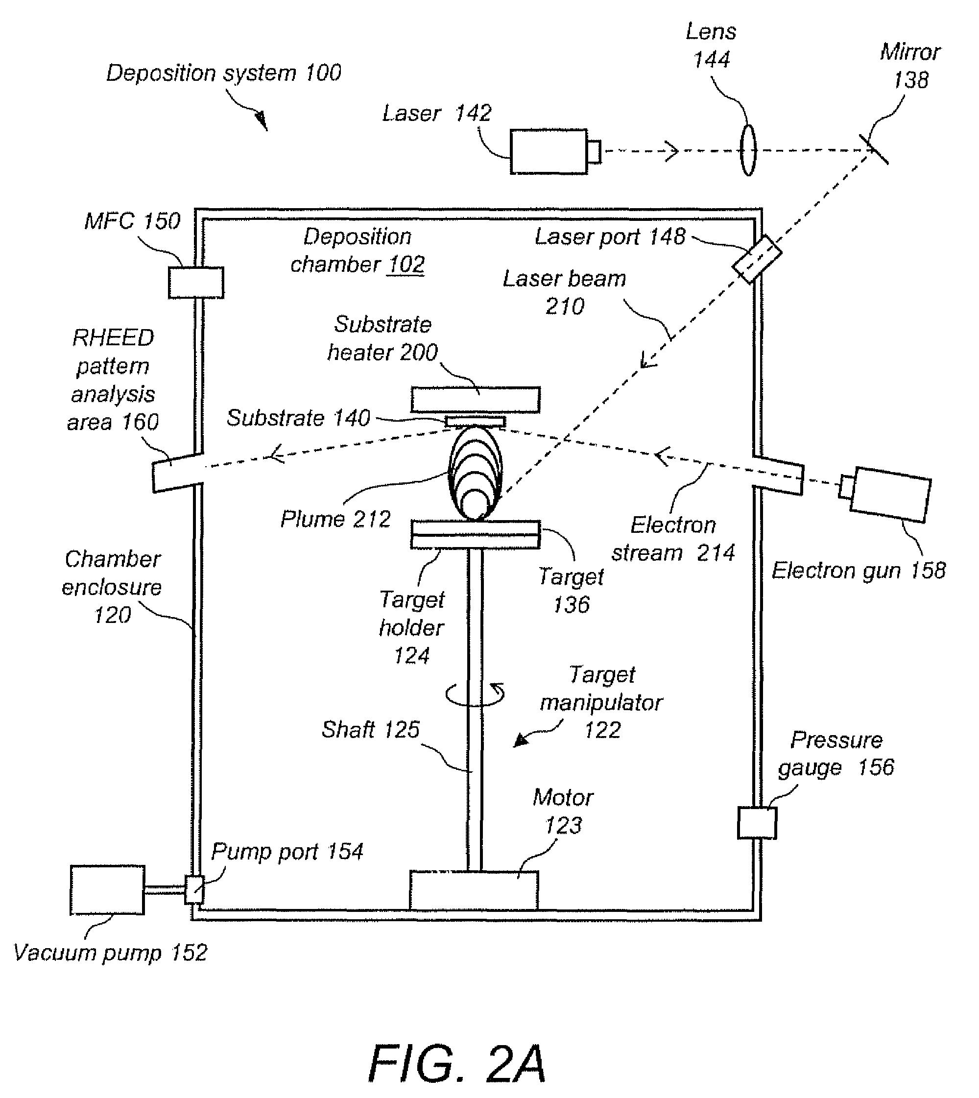
[0043]For use in a pulsed laser deposition (PLD) process, the multi-zone heater of the present invention includes passages that enable one or more laser beams to pass unimpeded to one or more targets, which otherwise would be obstructed by the size of such a substrate heater that is necessary to accommodate the increased deposition zone length necessary to a high throughput PLD system. The multi-zone heater also allows for accurate monitoring of the substrate temperature via thermocouples and an optical pathway disposed through its structure that enables a pyrometer to make temperature measurements to the non-coated side of the translating tape.
[0045]In operation, the multi-target manipulator apparatus, having multiple target holders upon which are placed multiple targets, respectively, allows multiple laser beams to impinge simultaneously upon the targets. As a result, multiple plumes of ablated material, to which a substrate is exposed for a predetermined time, are formed, thereby forming a film on the substrate. Furthermore, due to the appropriate spacing between the multiple target manipulators arranged in a line, the resulting plumes slightly overlap one to another and therefore ensure uniformity of film deposition over an expanded deposition zone length.

Problems solved by technology

As power demands continue to grow, older urban electric power systems in particular are being pushed to the limit of performance, requiring new solutions.
However, to date only short lengths of coated conductor wire samples have been fabricated at high performance levels with any of the conventional fabrication processes.
However, to date only short lengths of coated conductor wire samples have been fabricated at high performance levels using prior art vapor deposition processes and equipment.
While this represents a step toward the large-scale production of HTS coated tape, it is limited in its scalability.
To achieve significantly longer lengths of HTS coated tape the cylindrical substrate holder must increase in size accordingly, making it impractical to be housed within the main vapor deposition chamber.
Thus, a drawback of the vapor deposition process described in Youm is that the system is not easily scalable to produce long lengths (e.g., several kilometers) of HTS coated tape and is therefore not suited for the large-scale production of HTS coated wire.
A first challenge to the continuous deposition of HTS tapes utilizing a reel-to-reel tape transport system that is not overcome by Youm is the maintenance optimum tape tension throughout the extended deposition runs necessary to high-throughput systems.
This results in a variation in the target-to-substrate distance and a compromise of the thin film uniformity.
A second technical challenge to the continuous deposition of HTS tapes utilizing a reel-to-reel tape transport system that is not overcome by Youm is the maintenance of the tape at the optimal speed throughout extended deposition runs.
Lateral, as well as longitudinal, movement of the tape results in an inconsistent and non-uniform deposition resulting in variations in film thickness.
The importance of film uniformity cannot be an overemphasized: if there is an insufficient superconducting quality at a single point over the entire length of a few hundred meters of tape, the current carrying capacity of the entire length of tape is compromised.
Further, any elements that serve to position the tape must do so in such a way as to not induce stress or strain in the tape, which may damage the delicate thin films
Another technical challenge not overcome by Youm is how to wind the tape onto a spool subsequent to its undergoing the deposition process without damaging the delicate thin film housed thereon.
The ceramic grains of superconducting films may fracture if bent beyond a certain strain, which may result in a decrease in the critical current-carrying capacity of the finished superconductor tape.
However, in the case of a continuously translating substrate as is necessary for a continuous flow manufacturing process, it is difficult to maintain a uniform temperature profile using resistive heaters as disclosed by the prior art, Any local loss of contact with the heating element by a rapidly moving substrate can cause large temperature variations and in turn inhomogeneities in the coating film.
Consequently, a technical challenge to overcome is how to heat a rapidly moving substrate in a continuous flow high-throughput manufacturing process for producing long lengths of HTS-coated wire.
Current substrate heaters do not provide multiple heating zones with differing temperature ranges as required for continuous flow manufacturing of HTS-coated wire and thus are not suited for use in the large-scale production of HTS-coated wire,
Conventional target manipulators are therefore of limited use in a multilaser beam PLD application.
Although it is conceivable that multiple lasers could be focused on all targets simultaneously, it is not practical for a continuous flow application in which a substrate tape is translating in a straight line, thereby requiring the targets to be arranged in a straight line.
A further limitation is that Kim et al.
This type of multi-target manipulator is therefore not suited for use in the large-scale production of HTS-coated wire utilizing a continuously translating substrate through a deposition chamber.
However, using such an arrangement of several conventional target manipulators in a multi-laser beam PLD system is very costly and therefore not practical.
Also, conventional target manipulators occupy lot of space and as a result, there will be large gaps between targets.
This will result in large gaps between plumes from the targets when used with multiple lasers.
Consequently, this arrangement of several conventional target manipulators is not economically or practically suited for use in the large-scale production of HTS-coated wire.

Method used


Image

  • High throughput continuous pulsed laser deposition process
  • High throughput continuous pulsed laser deposition process
  • High throughput continuous pulsed laser deposition process

Examples


first embodiment

[0120]In a first embodiment, FIGS. 5A and 5B illustrate a top and side view, respectively, of a multi-manipulator assembly 350 of the present invention. The multi-manipulator assembly 350 includes a rotator assembly 310a, a rotator assembly 310b, and a rotator assembly 310c. The rotator assembly 310a further includes a motor 306a mechanically connected to a target holder 124a via a shaft 316a. The rotator assembly 310b further includes a motor 306b mechanically connected to a target holder 124b via a shaft 316b. Likewise, the rotator assembly 310c further includes a motor 306c mechanically connected to a target holder 124c via a shaft 316c. The rotator assemblies 310a, 310b, and 310c are mechanically interconnected by feeding the shafts 316a, 316b, and 316c, respectively, through a support bar 318. The shafts 316a, 316b, and 316c may be solid shafts that pass through the support bar 318 and allowed to rotate via conventional bearing assemblies inserted within the support bar 318. Al...

second embodiment

[0128]In a second embodiment, FIGS. 6A and 6B illustrate a top and side view, respectively, of a multi-manipulator assembly 400 of the present invention. The multi-manipulator assembly 400 is identical to the multi-manipulator assembly 350 of FIGS. 5A and 5B, differing only in that the rotator assemblies 310a, 310b, and 310c are mounted on a support plate 410 instead of interconnecting with the support bar 318. As in FIGS. 5A and 5B, a plurality of the connection rods 320a, 320b, 320c, and 320d are mechanically connected to the support plate 410 at each corner. The position and orientation of the connection rods 320a, 320b, 320c, and 320d is not limited to that shown in FIGS. 6A and 6B. Alternative positions and orientations are possible. As in FIGS. 5A and 5B, a variable-speed actuator (not shown) is mechanically attached to the connection rods 320a, 320b, 320c, and 320d.

[0129]The operation is identical to that of the multi-manipulator assembly 350 described in FIGS. 5A and 5B, di...


PUM

PropertyMeasurementUnit
lengthaaaaaaaaaa
lengthaaaaaaaaaa
temperatureaaaaaaaaaa

Abstract

A method includes feeding an uncoated substrate from a payout spool into a multi-chambered vacuum apparatus. The vacuum apparatus includes a plurality of deposition chambers defining an extended deposition zone, a multi-zone substrate heater located within the extended deposition zone, and multiple high-temperature superconductor (HTS) targets located within and being arranged linearly along the extended deposition zone. The multiple HTS targets include a first and second HTS target. The first and second HTS targets include a HTS material. The method farther includes translating the uncoated substrate along a translation path through the plurality of deposition chambers, impinging multiple laser beams simultaneously upon the multiple HTS targets and forming multiple overlapping plumes of HTS material within the extended deposition zone, depositing HTS material on a first major surface of the uncoated substrate to provide a coated substrate, and winding the coated substrate onto a take-up spool.

Description

CROSS-REFERENCE TO RELATED APPLICATION(S)[0001]The present application is a divisional application of U.S. application Ser. No. 10 / 602,294 filed Jun. 23, 2003 now abandoned, which is incorporated herein by reference in its entirety.FIELD OF THE INVENTION[0002]The present invention relates to an apparatus and method for forming a high-temperature superconducting film on a long tape substrate at speeds suitable for large-scale production, includes a spooling system for use in a high-throughput, continuous pulsed laser deposition (PLD) process.BACKGROUND OF THE INVENTION[0003]In the past three decades, electricity has risen from 25% to 40% of end-use energy consumption in the United States. With this rising demand for power comes an increasingly critical requirement for highly reliable, high quality power. As power demands continue to grow, older urban electric power systems in particular are being pushed to the limit of performance, requiring new solutions.[0004]Wire forms the basic b...

Claims


Application Information

Patent Timeline
Patent Type & Authority Patents(United States)
IPC IPC(8): B05D5/12C23C14/08C23C14/28C23C14/56H01L39/24
CPCC23C14/087C23C14/28C23C14/562H01L39/2448H10N60/0521
Inventor SELVAMANICKAM, VENKATLI, YIJIEPARK, CHAN
Owner SUPERPOWER INC
Learn More