Flat spiral capillary column assembly with thermal modulator

a capillary column and thermal modulator technology, applied in the field of gas chromatography, can solve the problems of high cost, large energy waste, and very limited results, and achieve the effect of reducing the the overall temperature of the capillary separation column

Inactive Publication Date: 2009-04-07
ROQUES NED J
View PDF17 Cites 10 Cited by
  • Summary
  • Abstract
  • Description
  • Claims
  • Application Information

AI Technical Summary

Benefits of technology

[0018]It is a fundamental object of this invention to provide a gas chromatography capillary separation column assembly which is planar in nature, compact, low in thermal mass, heats evenly and efficiently across its entire surface area, requires relatively little power to heat and cool, and can be easily and accurately manufactured.
[0031]It is still further an object of this invention to provide a capillary column assembly that is adhesively or mechanically attached to a thermal modulator that is a thermoelectric Peltier device. Because of the extremely compact, flat nature of the capillary separation column assemblies described herein, long enough sections of capillary column material can be coiled into a space small enough to fit on the surface of commercially available Peltier devices such that sub-ambient temperature programmed gas chromatography can be performed in a very efficient manner. Peltier devices are now available that can withstand temperatures up to 225 degrees C. This kind of sub-ambient chromatography has traditionally been confined to the laboratory where large refrigeration systems are required and use substantial amounts of power or where large tanks of liquid coolant such as liquid nitrogen and liquid carbon dioxide are used to cool a conventional GC oven containing a wire-rack wound capillary column assembly. With a capillary separation column assembly attached, the Peltier device can operate as a cooling and heating device depending on the direction of current flow applied to the device. Chemical compounds that would routinely be inseparable at ambient temperatures due to low retention factors, can now be separated with the overall temperature of the capillary separation column reduced. With the temperature of the capillary separation column reduced even further, the device can function as a trap for concentrating chemical samples, and then by heating the Peltier device, it can act as a separation column for performing the chemical analysis on the same concentrated sample. This can extend the chemical separating range of capillary separation columns to a significant enough degree that what might normally require two different separation columns to separate a given set of compounds can now be done with one or what might normally require an extra long length of capillary column material to separate a given set of compounds can now be performed on a capillary column a fraction of the length.

Problems solved by technology

This proved to be very limiting if a chemical sample to be analyzed contained compounds with a broad boiling point distribution.
This results in very even heating of the separation column along its entire length and consequently produces very efficient chromatographic performance, but at a significant cost.
Much energy is wasted.
Because of the large amount of power being consumed to heat the oven, large amounts of insulation must be employed to contain the heat, consequently, the bulky nature of conventional gas chromatographs can be directly attributed to the oven / insulation combination.
Due to the large amount of power and space required to thermally modulate and house the capillary separation column when coiled on a conventional wire rack, this design is impractical for use in miniaturized or portable / transportable gas chromatographic systems.
While power consumption was reduced, these gas chromatographs still consume relatively large amounts of power, on the order of a kilowatt, and are mostly confined to isothermal oven operation or very slow temperature programming rates with limited upper temperatures when being used in a transportable mode where power supply is a relevant issue.
This severely limits the range of compounds that can be analyzed as well as increases the amount of time necessary for each analytical cycle.
While this development reduced the size of the gas chromatograph, the power consumption continues to remain high at around 1 kW.
This technique provided for a large reduction in power consumption versus convection oven designs but suffers from inconsistencies in the thin conductive film thickness, as well as damage to the thin conductive film during handling, coiling and heating / cooling cycles.
These inconsistencies in film thickness along with damaged portions of the conduction film act to create variances in the resistance across the length of the capillary column which, when current is passed through the conductive film, causes localized hot spots to form on the capillary column surface.
A very negative consequence of these hot spots is a non-uniform distribution of thermal energy across the length of the capillary column and ultimately an overall reduction in the chromatographic separating efficiency of the capillary column material.
Also, when larger currents are passed through the thin conductive film to achieve faster temperature programming rates or to maintain the capillary column at higher temperatures, the localized hot spots begin to hasten the degradation of the thin conducting film which eventually leads to a failure of the heating system.
In addition, the degree to which the capillary column can be compactly contained is limited by the insulation needed to protect successive coils from electrical short circuits, especially at higher temperatures above 200 degrees C., and the minimum bend radius that the thin conductive film can withstand before breakage occurs.
This limitation usually results in a cylinder shaped arrangement of coils with a minimum radius of approximately 7.5 cm and cylinder height dependent on the length of capillary column needed.
Yet another drawback to using this method to thermally modulate the capillary column stems from the fact that the deposition of thin conductive films to the surface of fused silica capillary column material requires an intricate, detailed process that further complicates the manufacturing of the capillary column, thus severely limiting the variety of capillary column types available and manufactures willing to produce them.
While this technique solves the problem associated with the thin resistive film breakdown and hot spots of the previously discussed technique and consequently produces even thermal distribution across the length of the capillary column, the problem of having to electrically isolate successive coils from one another continues to limit the overall compactness of the design.
Additionally, the extra thermal mass contributed by the resistively heated metal sheath in which the capillary column is placed, dramatically increases the power consumption of the device.
It is stated in their patent that “a power supply capable of delivering up to 96 Volts at 12 Amps provides sufficient power to heat the tube (metal sheath) to desired temperatures” which is on the order of approximately 1 kW and approaching conventional convection oven power requirements, once again making it an impractical choice for the miniaturization of temperature programmed gas chromatographs.
However, due to the extra steps involved with inserting the heater wire into a length of insulating sheath and then inserting the bundle of capillary column material, fragile sensor wire, and sheathed heater wire into a second insulating sheath, it becomes a very tedious, nearly impractical exercise to manufacture a separation column assembly in this manner any longer than 3 meters.
This limitation in column length reduces the range of chemicals that can be separated in a single analysis and, while the power consumption is greatly reduced when compared to a conventional GC oven, in reality the column assembly still consumes enough power to prevent its use in truly portable, battery operated, temperature programmable GC designs.
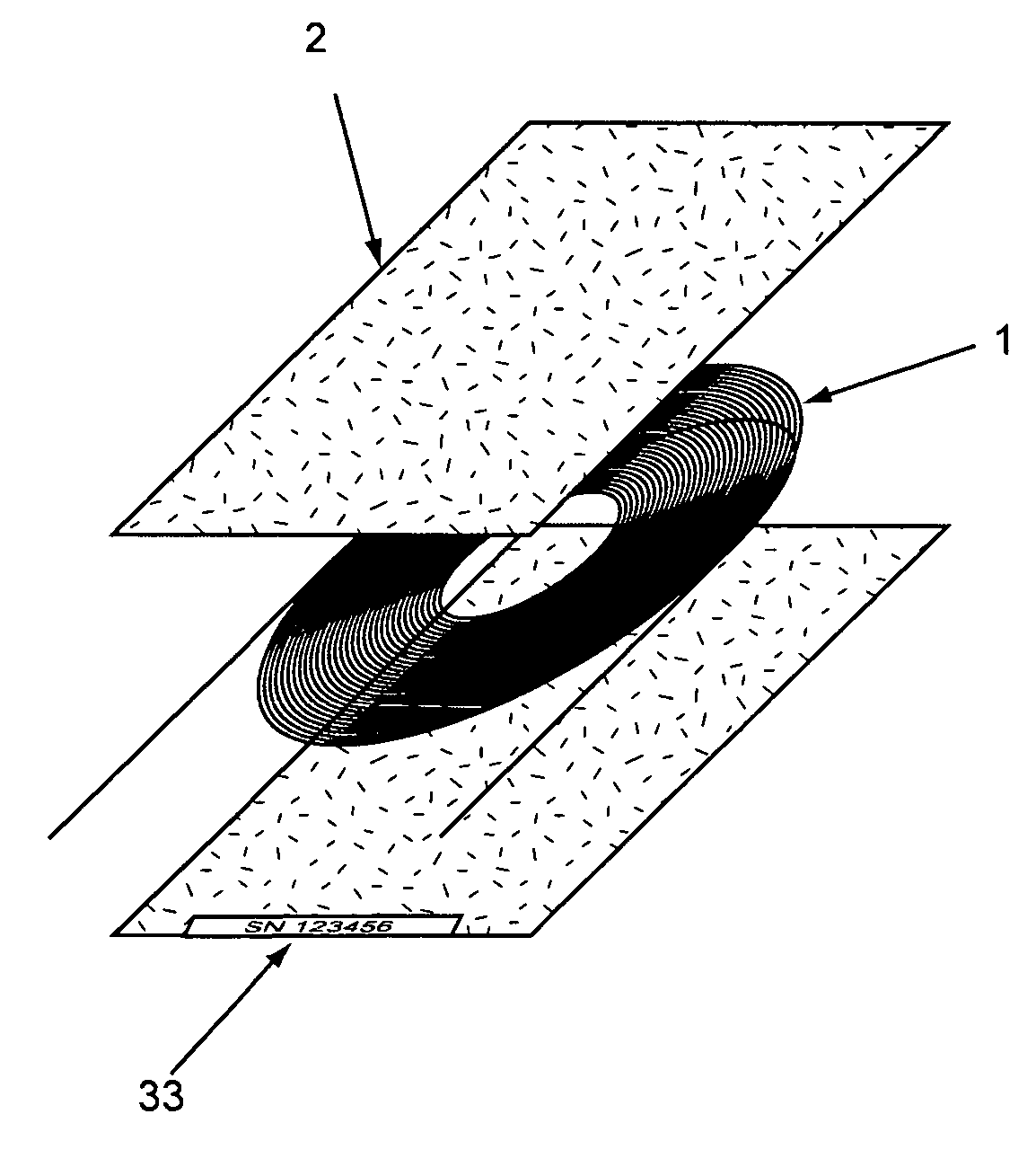
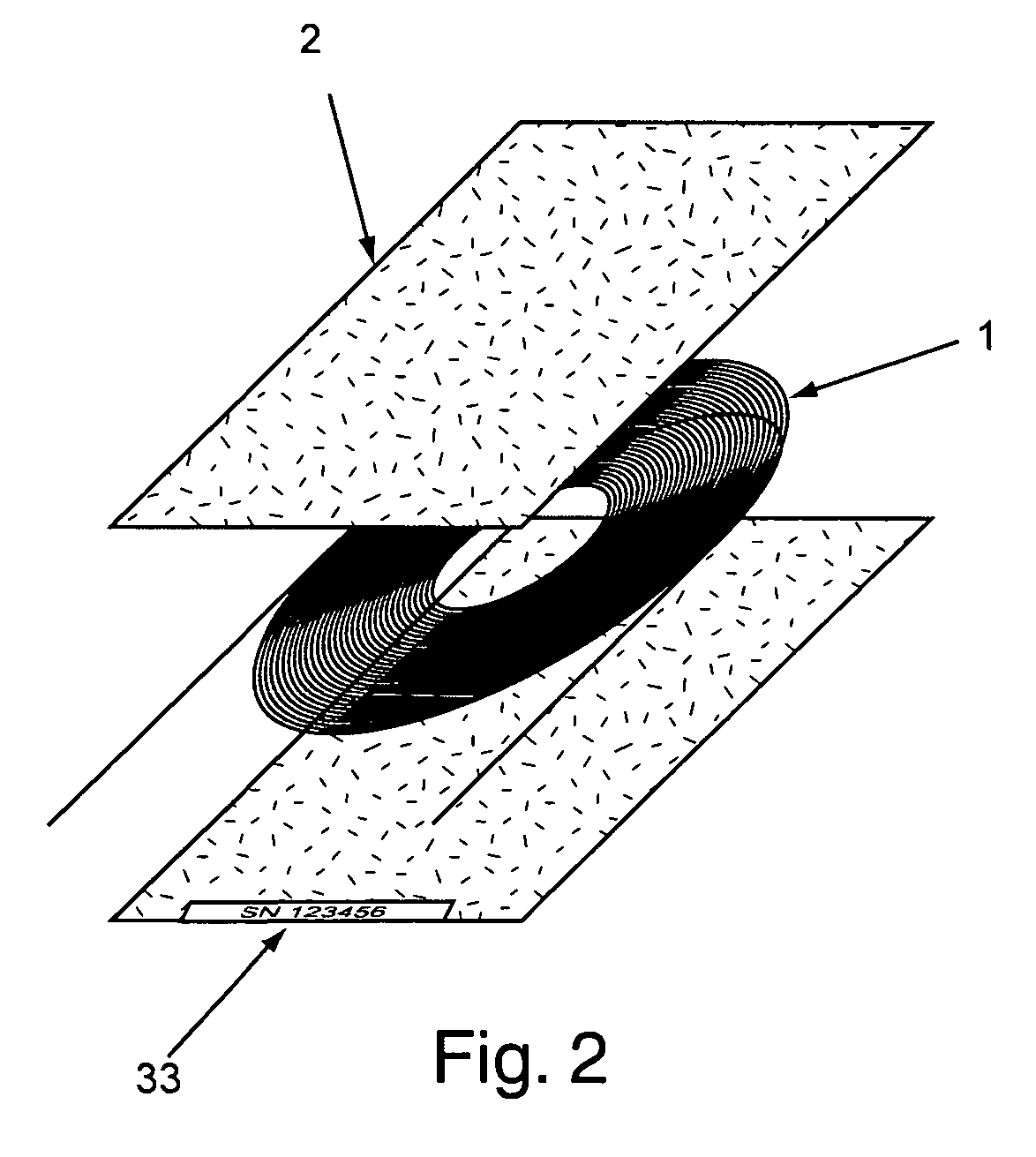
Besides the complexity of manufacturing such an assembly, one drawback that this design presents deals with the round cross-sectional nature of a tightly packed, randomly arranged series of elements in a toroidal geometry.
Because of the randomly arranged coils within the torus geometry, this results in uneven heating across the entire length of the capillary column and as a consequence, a reduction in the chromatographic separating efficiency of the capillary column material.
Depending on the type of chemical analysis being performed, this could result in unacceptable performance variations after a capillary column assembly change is made.
A second general problem associated with the various “single unit” capillary column assembly designs deals with the extra manufacturing burden generated from having to couple all of the various elements into a precise orientation and then the extra steps involved attaching them to insulated support structures and electrical lead connections.
This usually involves having a person with expert technical skill make the column assemblies and ultimately a much higher end cost to the consumer.
While this technique may result in a minimal amount of power being needed to thermally modulate the separation column in a fairly compact form, the amount of specialized hardware necessary to perform this function make it an expensive, impractical choice for use in miniaturized portable / transportable temperature programmed gas chromatographs where ruggedness and simplicity of design are better suited.
This is most likely done in order to provide a more even thermal energy distribution from the heat lamp to the surface of the capillary separation column, however, this results in a much larger than necessary power requirement to heat the device.

Method used


Image

  • Flat spiral capillary column assembly with thermal modulator
  • Flat spiral capillary column assembly with thermal modulator
  • Flat spiral capillary column assembly with thermal modulator

Examples


Embodiment Construction

[0047]It can be shown that from FIGS. 1-15 a high-efficiency, planar capillary column assembly 15 with an integrated thermal modulator 17 is presented for use with gas chromatographic devices. Such an integrated capillary separation column system is especially beneficial for use in portable / transportable gas chromatographic systems where limited space and power are available yet maximal chromatographic results are needed. Because of its compact nature the capillary column assembly 15 and thermal modulator 17 can together be adapted for use in a wide variety of gas chromatographic devices and should not be limited to a specific class of instruments such as portable / transportable, laboratory or process GC.

[0048]The planar capillary column assembly 15 described herein is comprised of a length of capillary column material 1 which can be made of such material as fused silica tubing or metal capillary tubing and is readily, and easily obtainable from several different manufactures such as...


PUM


Abstract

The gas chromatography (GC) column assembly described herein consists of capillary GC column material, such as fused silica or metal capillary tubing, which is constrained to lie in a flat, ordered, spiral pattern and then encased between two thin opposing surfaces. The resulting column assembly is flat, dimensionally stable and can be very efficiently thermally modulated. The resulting column assembly also takes up very little space, has very little thermal mass, and can be easily and accurately manufactured. The column assembly can be adapted for chromatographic use by affixing it to the surface of a thermal modulator described herein by means of adhesive force or by mechanical compression, and then by attaching the free ends of the exposed column material to the input and output ports of the chromatographic device.

Description

[0001]This application claims the benefit of U.S. Provisional Application No. 60 / 677665 filed May 3, 2005.BACKGROUND OF THE INVENTION[0002]1. Field of the Invention[0003]The invention contained herein pertains to the field of gas chromatography and more specifically to compact capillary column assemblies and the thermal modulators used to modulate the temperature of the compact capillary column assemblies in order for chemical compounds to be optimally separated from one another. The invention is primarily concerned with thermally efficient, compact, dimensionally flat, rugged, low thermal mass capillary column assemblies of varying flat geometries and the attachment of such capillary column assemblies to various types of thermal modulators for integration with a wide variety of currently available gas chromatographic devices. It is the ultimate goal of this invention to provide the field of gas chromatography with a device that is extremely compact, consumes the smallest amount of ...

Claims


Application Information

Patent Timeline
Patent Type & Authority Patents(United States)
IPC IPC(8): B01D53/02
CPCG01N30/6095G01N30/6047G01N2030/0095G01N2030/303G01N2030/3053
Inventor ROQUES, NED J.
Owner ROQUES NED J
Why Eureka
Try Eureka