Continuous system for depositing films onto plastic bottles and method

a technology of film and plastic bottles, applied in the direction of chemical vapor deposition coating, vacuum evaporation coating, coating, etc., can solve the problems of limited gas supply capacity of pet, high moisture sensitive evoh, and difficulty in finding widespread acceptance, so as to reduce the process cycle time, avoid duplication of costs, and maximize the utilization efficiency of bottle processing equipmen

Active Publication Date: 2009-04-07
NANO SCALE SURFACE SYST
View PDF48 Cites 52 Cited by
  • Summary
  • Abstract
  • Description
  • Claims
  • Application Information

AI Technical Summary

Benefits of technology

[0023]The bottles are coated using the bottle processing apparatus in a continuous assembly line fashion at a high rate appropriate for commercial production environments. In one embodiment, the bottles are coated at a rate of at least 20,000 bph, e.g., 40,000 bph, thus maximizing

Problems solved by technology

One of the greatest challenges in the plastics packaging business has been the reduction of gas transfer through polymeric materials to either stop gases from ingressing into the packaged product, or to stop gases from egressing from the packaged product.
There have been many approaches attempted including new resin formulations and multi-layers of polymeric materials, but each has had problems finding widespread acceptance due to either the cost, non-recyclability or the performance.
Although widely used in rigid packaging, PET is limited in its ability to provide gas barrier to both gas coming into the product (gas ingress) and escaping (gas egress).
EVOH provides excellent oxygen barrier properties, however, EVOH is highly moisture sensitive and the barrier properties deteriorate with exposure to water.
Other materials such as nylon have also been investigated but have had issues with recyclability and cost.
Both of these materials have been successfully integrated into multi-layer structures, however, none have been demonstrated to be recyclable, and due to the high cost of the barrier materials, the overall cost of the package is outside of acceptable limits.
There are, however, few practical monolayer materials under development.
Further, there is still the significant issue of recycle of the monolayer, since the current recycle streams for polymers are set

Method used


Image

  • Continuous system for depositing films onto plastic bottles and method
  • Continuous system for depositing films onto plastic bottles and method
  • Continuous system for depositing films onto plastic bottles and method

Examples


Embodiment Construction

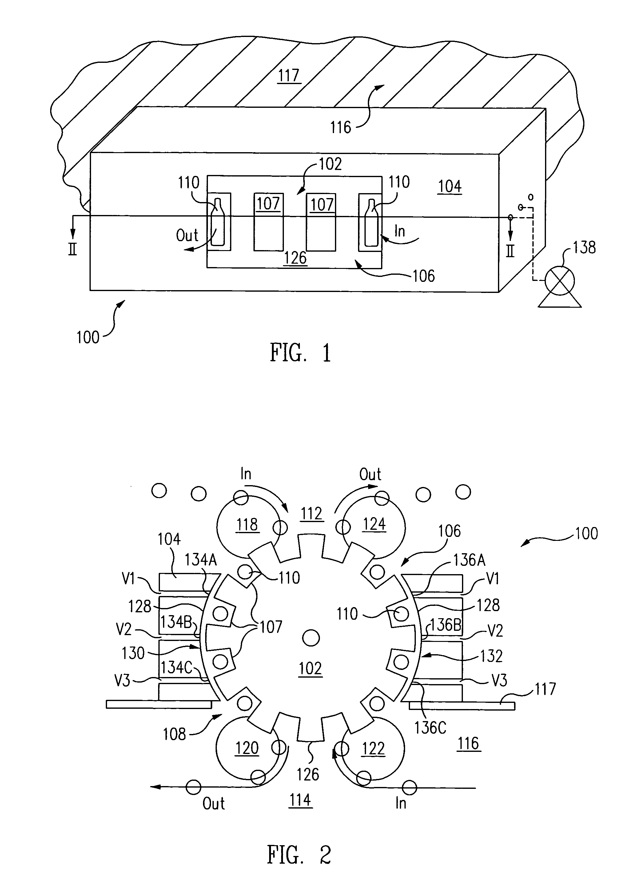
[0046]FIG. 1 is a perspective view of a rotary bottle vacuum transfer system 100 in accordance with one embodiment of the present invention. FIG. 2 is a cross-sectional view of rotary bottle vacuum transfer system 100 of FIG. 1 along the line II-II in accordance with one embodiment of the present invention.

[0047]Referring now to FIGS. 1 and 2 together, rotary bottle vacuum transfer system 100, sometimes called a rotary delivery mechanism, includes a rotary bottle transfer wheel 102 within a chamber 104. Chamber 104 includes an atmospheric port 106 and a vacuum port 108.

[0048]Bottles 110, e.g., PET bottles, are continuously transferred from an exterior region 112 at atmospheric pressure into rotary bottle vacuum transfer system 100 through atmospheric port 106. Bottles 110 are continuously brought from atmospheric pressure to a sub-atmospheric pressure, e.g., in the range of 1-1000 mTorr (10-100 mTorr in one embodiment), within bottle vacuum transfer system 100. Bottles 110 are conti...


PUM

PropertyMeasurementUnit
Dielectric polarization enthalpyaaaaaaaaaa
Pressureaaaaaaaaaa
Poweraaaaaaaaaa

Abstract

A bottle processing apparatus includes a rotary bottle vacuum transfer system and a bottle coating system. The rotary bottle vacuum transfer system takes bottles from atmospheric pressure and transfers the bottles to the bottle coating system at a sub-atmospheric pressure in a continuous assembly line fashion. In the bottle coating system, a thin film coating having barrier properties is formed on at least one surface of the bottles in a continuous assembly line fashion. After formation of the thin film coating, the rotary bottle vacuum transfer system returns the bottles from the sub-atmospheric pressure region of the bottle coating system back to atmospheric pressure in a continuous assembly line fashion.

Description

CROSS-REFERENCE TO RELATED APPLICATIONS[0001]This application claims the benefit of U.S. Provisional Application No. 60 / 525,313, filed on Nov. 25, 2003, entitled “SYSTEM AND METHOD FOR DEPOSITING INORGANIC THIN FILMS ONTO THE INTERIOR OF PLASTIC BOTTLES”, of John T. Felts, which is herein incorporated by reference in its entirety.BACKGROUND OF THE INVENTION[0002]1. Field of the Invention[0003]This invention relates to a system and method for depositing oxide and other inorganic materials onto the inside surface of 3 dimensional shapes, such as bottles, at high rates appropriate for production environments.[0004]2. Description of the Related Art[0005]One of the greatest challenges in the plastics packaging business has been the reduction of gas transfer through polymeric materials to either stop gases from ingressing into the packaged product, or to stop gases from egressing from the packaged product. There have been many approaches attempted including new resin formulations and mult...

Claims


Application Information

Patent Timeline
IPC IPC(8): C23C16/00C23C16/455C23C16/458C23C16/50C23C16/503C23C16/54
CPCC23C14/046C23C14/56
Inventor FELTS, JOHN T.
Owner NANO SCALE SURFACE SYST
Why Eureka
Try Eureka