Multipath laser apparatus using a solid-state slab laser rod

a laser apparatus and multi-path technology, applied in the direction of laser cooling arrangements, laser details, excitation process/apparatus, etc., can solve the problems of poor efficiency of electricity to light conversion by the lamp itself, large power consumption of laser apparatus, and insufficient power consumption

Inactive Publication Date: 2009-04-07
NAT INST OF INFORMATION & COMM TECH
View PDF16 Cites 10 Cited by
  • Summary
  • Abstract
  • Description
  • Claims
  • Application Information

AI Technical Summary

Benefits of technology

[0025]The present invention relates to a laser rod wherein laser light that is incident to the laser rod is totally reflected at the incident-light end face and light exit end face of the laser rod, passes back through the interior of the laser rod a plurality of times, e.g., three times, and then exits. As a result of the disposition of this optical path, a high conversion rate from excitation light to laser light and a high laser gain are obtained, so the drawbacks of the prior-art laser rods can be improved.
[0042]In another aspect, the present invention provides a laser apparatus using a solid-state slab laser rod that has a cross section along the optical path in a shape equivalent to a trapezoid X comprising a side face AX, side face BX, upper base face CX and lower base face DX joined to a similar trapezoid Y comprising a side face AY, side face BY, upper base face CY and lower base face DY, being provided with eight or more planes containing the side face AX, side face BX, upper base face CX, lower base face DX, side face AY, side face BY, upper base face CY and lower base face DY, and that has a light amplifying effect, comprising.
[0051]In another aspect, the present invention provides a laser apparatus using a solid-state slab laser rod that has a cross section along the optical path in a shape equivalent to a trapezoid X comprising a side face AX, side face BX, face CX and face DX joined to a similar trapezoid Y comprising a side face AY, side face BY, face CY and face DY, being provided with eight or more planes containing the side face AX, side face BX, face CX face DX, side face AY, side face BY, face CY and face DY, and that has a light amplifying effect, comprising:
[0066]In another aspect, the present invention provides a laser apparatus using a solid-state slab laser rod that has a cross section along the optical path in a shape equivalent to a right trapezoid having two adjacent right angles, where the two right trapezoids formed by bisecting this right trapezoid along a line parallel to its base are a trapezoid X comprising a side face AX, side face BX, upper base face CX and lower base face DX and a similar trapezoid Y comprising a side face AY, side face BY, upper base face CY and lower base face DY, where the right trapezoids are such that lower base face DX lies atop upper base face CY, being provided with eight or more planes containing the side face AX, side face BX, upper base face CX, side face AY, side face BY and lower base face DY, and that has a light amplifying effect, comprising:
[0082]In another aspect, the present invention provides a laser apparatus using a solid-state slab laser rod that has a cross section along the optical path in a shape equivalent to a trapezoid X comprising a side face AX, side face BX, upper base face CX and lower base face DX and a similar trapezoid Y comprising a side face AY, side face BY, upper base face CY and lower base face DY, where the lower base face DX lies atop lower base face DX, being provided with eight or more planes containing the side face AX, side face BX, upper base face CX, side face AY, side face BY and upper base face CY, and that has a light amplifying effect, comprising:
[0098]The laser apparatus using a multipath solid-state slab laser rod according to the present invention is particularly such wherein the solid-state slab laser rod has a light amplifying effect and wherein excitation light is shined from either face C or face D or both faces and wherein a thermal conductor is provided on either face E or face F or both faces, thereby radiating heat.

Problems solved by technology

In lamp-excited lasers, the efficiency of the conversion of electricity to light by the lamp itself is poor and its light-emission spectrum is wide, so much of the light cannot be absorbed by the laser rod, so the laser apparatus must have a large power consumption.
In laser diode (LD)-excited lasers, the conversion efficiency of the LD itself is high and the spectrum of the emitted light is tuned to the absorption peak of the rod, so a higher conversion efficiency is obtained, but this is still not enough.
However, if the doping of laser-active ions is increased, disturbances in the refractive index distribution of the laser rod typically become evident.
In addition, drops in optical quality such as reduced high-level lifetime in excitation occur more readily.
These manifestations of disturbances in the refractive index distribution and drops in optical quality may become the cause of deterioration in the transverse modes of the laser beam thus obtained, and bring about performance drops as a laser medium.
There are thus limits how much the doping can be increased.
In addition, in fundamentally transverse mode-oscillating lasers and high-power lasers, if there is heating within the interior of the laser rod, then this generates temperature distributions in the interior, thus giving the laser medium distortion.
This distortion gives rise to decreased quality in the laser rod, birefringence and the like, so the transverse modes of oscillation diverge from the fundamental transverse mode.
However, these are contradictory conditions so reconciling them is difficult in a typical laser apparatus according to the prior art.
In addition, in order to effectively use the energy stored within the laser rod, it becomes necessary to make the laser beam cross section equal over all sections of the laser rod, thus reducing the optical strength for induced emission.
However, the number of optical components required to provide multiple optical paths in these laser apparatus becomes large.
They thus have drawbacks in that the structure of the laser apparatus becomes complex and the size of the apparatus itself becomes large.
Moreover, because optical losses are unavoidable in the non-reflective coating at the laser rod ends and in the reflection by reflectors, these losses accumulate each time the laser light travels back and forth between the ends of the laser rod, resulting in the effect of the increased laser gain being reduced.
Moreover, with the conventional multipath devices, adjacent optical paths vary in direction by only a very small amount, so they had a drawback in that the path distribution within the rod could not be adequately averaged.
In this manner, multiple optical paths are used in laser apparatus in order to increase the energy conversion efficiency of the laser apparatus, but the number of optical components required to provide multiple optical paths in these laser apparatus becomes large, and moreover precise adjustment is required in their placement, so there are drawbacks in that the structure of the laser apparatus becomes complex and the size of the apparatus itself becomes large.
For this reason, with nonlinear optical elements, they are fundamentally manufactured so as to have a straight, one-pass optical path or a single back-and-forth optical path, and thus they do not have multiple optical paths and do not give adequate wavelength conversion efficiency.

Method used


Image

  • Multipath laser apparatus using a solid-state slab laser rod
  • Multipath laser apparatus using a solid-state slab laser rod
  • Multipath laser apparatus using a solid-state slab laser rod

Examples


embodiment 1

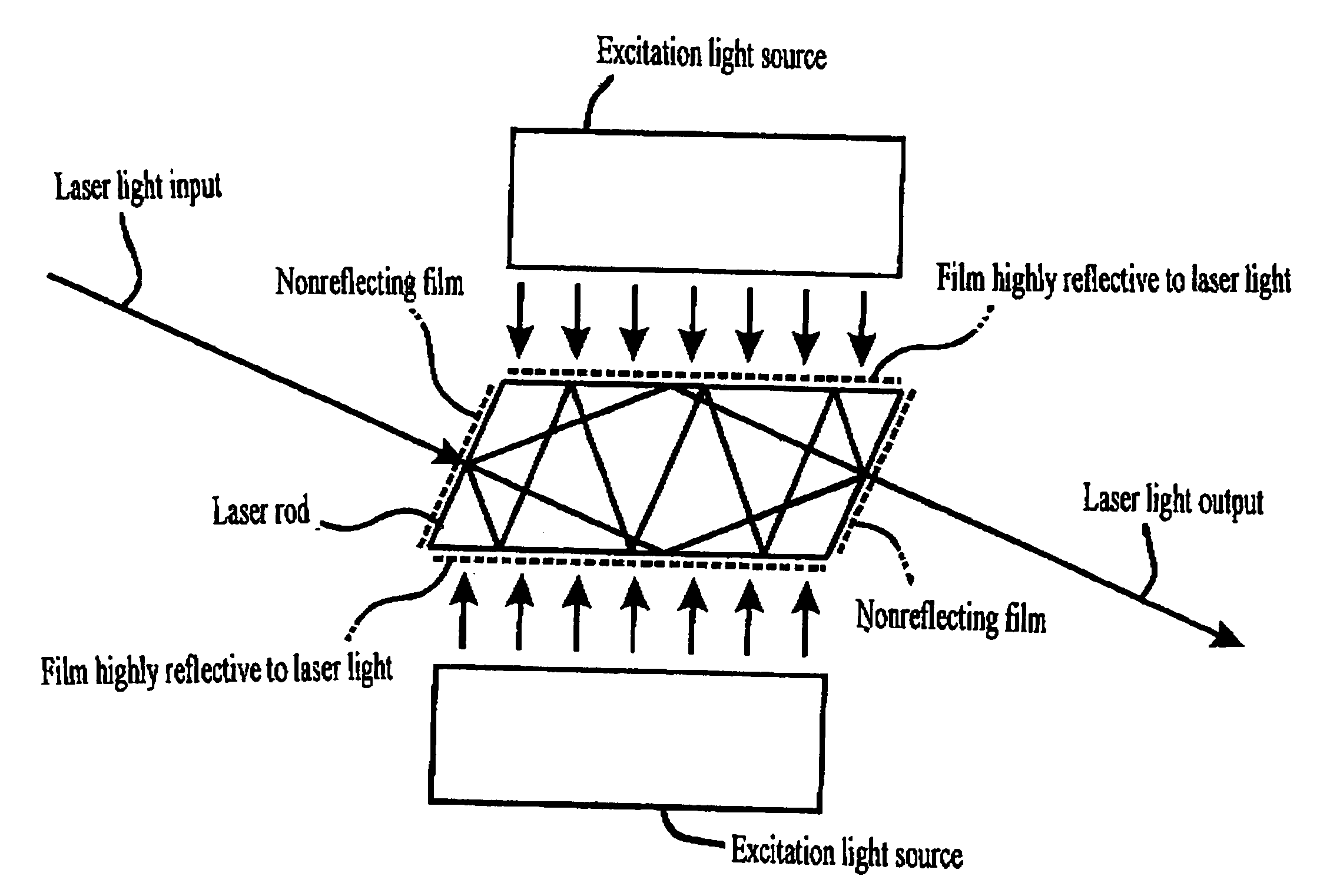
[0125]The solid-state slab laser rod in the laser apparatus according to the present invention has a cross section in the shape of a long, thin trapezoid- or parallelogram-shaped slab as shown in FIG. 3 or FIG. 4. Each of the four faces 10, 11, 12 and 13 perpendicular to the plane of the paper is optically polished and a laser light-reflecting film is applied to the upper and lower long side faces 12 and 13. Laser light does not come into contact with the two faces that are parallel to the plane of the paper, so they may be either polished faces or left as rough faces.

[0126]A light beam 1 that is incident at the Brewster angle upon end face 10 of the laser rod travels along path 2 within the interior of the rod as its initial optical path, being reflected by the side faces until reaching end face 11. Here, end face 11 is inclined with respect to the central axis of the rod, so the light is totally reflected and then travels along path 3 at a larger angle from the central axis as its...

embodiment 2

Linking in Series

[0150]Long rods disposed with the same triple paths can be manufactured by using the laser rods described above as basic cells, and conceptually linking identical cells in series at their end faces. In order to construct a triple path, it is necessary to add two basic cells at a time to the basic cell. This is in order to maintain the relationship of odd and even numbers in the number of reflections at the side faces present in the basic cells also in the linked rods. FIGS. 7 and 8 show examples of laser rods formed by linking three each of the basic cells with a number of side-face reflections of (2, 3) and (3, 4).

[0151]In the case of trapezoidal basic cells, they are linked linearly by vertically inverting each one in sequence. Parallelogram-shaped basic cells are linked without inverting.

embodiment 3

Linking in Parallel

[0152]Alternately, triple or higher multiple paths can be disposed in rods formed by linking two basic cells in parallel at their side faces. Trapezoidal basic cells can be linked so that they are symmetrical about the connected faces. The completed rod has a hexagonal cross section. FIG. 9 shows an example of the linking of basic cells with numbers of side-face reflections of (2, 3). Two sets of triple paths are formed in this rod.

[0153]Two parallelogram-shaped basic cells are linked by the linear translation of one of the basic cells. The completed parallel-linked rod becomes a rod with a parallelogram-shaped cross section, as expected. FIG. 10 shows an example of the linking of basic cells with numbers of side-face reflections of (3, 4). One set of quintuple paths is formed in this rod.

[0154]In the above linked rods and those to be presented hereinafter, the way of thinking of the number of side-face reflections is to be such that when light passes through the ...


PUM


Abstract

A laser apparatus has a multipath solid-state slab laser rod and an excitation source that excites it, and uses a solid-state slab laser rod that has a trapezoid or parallelogram-shaped cross section along the optical path, that is provided with six or more faces and that has a light amplifying effect or a nonlinear optical effect. The light that is incident to the laser rod is totally reflected at the incident-light end face and exit end face of the laser rod, passes back through the interior of the laser rod a plurality of times, e.g., three times, and then exits. For light amplification, excitation light is irradiated from the side face. In addition, for nonlinear optical effects, the z-axis of a nonlinear optical crystal is disposed so as to be orthogonal to the plane of the optical path, and the temperature of the solid-state slab laser rod is kept at the phase-matching temperature. This laser apparatus of this configuration solves drawbacks of prior-art laser rods so that the high conversion rate from excitation light to laser light is obtained at a high laser gain.

Description

BACKGROUND OF THE INVENTION[0001]1. Field of the Invention[0002]This invention relates to a multipath laser apparatus using a solid-state slab laser rod that is able to implement a solid-state laser apparatus with a high efficiency in the conversion of excitation light to laser light, and can be applied to Nd:YAG laser apparatus, Nd:YLF laser apparatus and Yb:YAG laser apparatus, for example.[0003]2. Description of the Prior Art[0004]The efficiency of conversion of electrical input to laser output in a solid-state laser apparatus is the most important among various factors affecting the performance of a laser. In lamp-excited lasers, the efficiency of the conversion of electricity to light by the lamp itself is poor and its light-emission spectrum is wide, so much of the light cannot be absorbed by the laser rod, so the laser apparatus must have a large power consumption. In laser diode (LD)-excited lasers, the conversion efficiency of the LD itself is high and the spectrum of the e...

Claims


Application Information

Patent Timeline
Patent Type & Authority Patents(United States)
IPC IPC(8): H01S3/06
CPCH01S3/0606H01S3/2325H01S3/0615H01S3/0623H01S3/0625H01S3/063H01S3/08095H01S3/093H01S3/1611H01S3/1643H01S3/1653
Inventor ISHIZU, MITSUO
Owner NAT INST OF INFORMATION & COMM TECH
Why Eureka
Try Eureka