Dual stage nitrogen rejection from liquefied natural gas

a technology of liquefied natural gas and nitrogen rejection, which is applied in the direction of lighting and heating apparatus, refrigeration machines, solidification, etc., can solve the problem of low nitrogen tolerance in the fuel gas, and achieve the effect of minimal additional equipment and minimal impact on plant performan

Active Publication Date: 2009-04-21
AIR PROD & CHEM INC
View PDF34 Cites 63 Cited by
  • Summary
  • Abstract
  • Description
  • Claims
  • Application Information

AI Technical Summary

Benefits of technology

[0022]It is an object of the present invention to provide for reject of part of the nitrogen from any LNG process with minimal additional equipment and minimum impact on plant performance. This can be achieved by the invention without any changes to the configuration of the heat transfer equipment for the production of LNG and with limited additional equipment. In particular, the invention avoids the necessity of an additional heat pump compressor and permits end product LNG to be used to operate a nitrogen separation column condenser.

Problems solved by technology

However, more environmentally friendly low nitrogen oxide (NOX) burners for these turbines have a lower tolerance for nitrogen in the fuel gas than previously used burners.

Method used


Image

  • Dual stage nitrogen rejection from liquefied natural gas
  • Dual stage nitrogen rejection from liquefied natural gas
  • Dual stage nitrogen rejection from liquefied natural gas

Examples


example 1

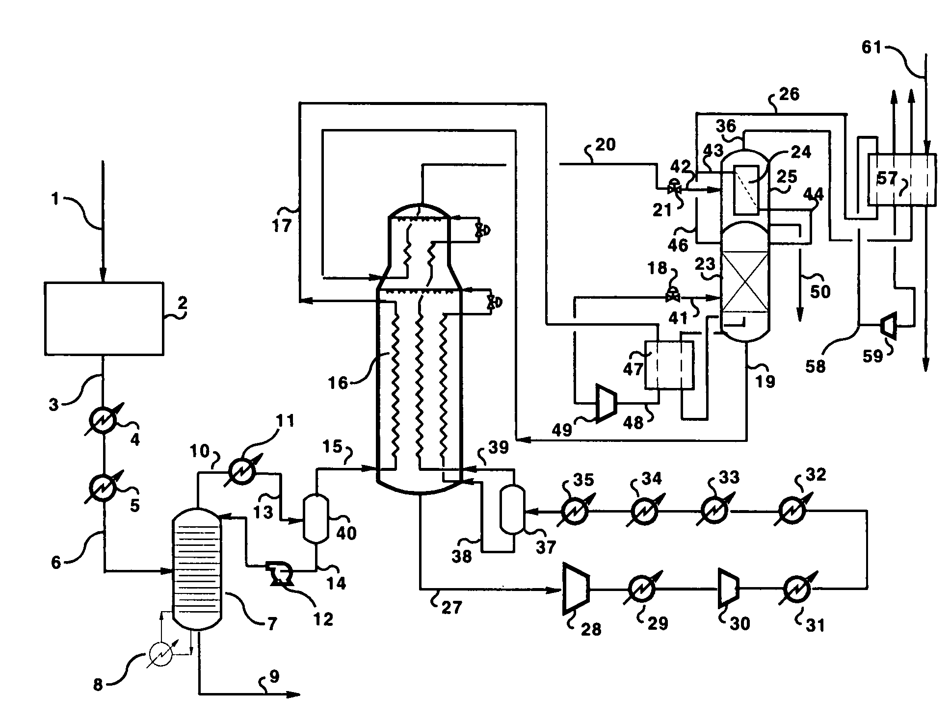
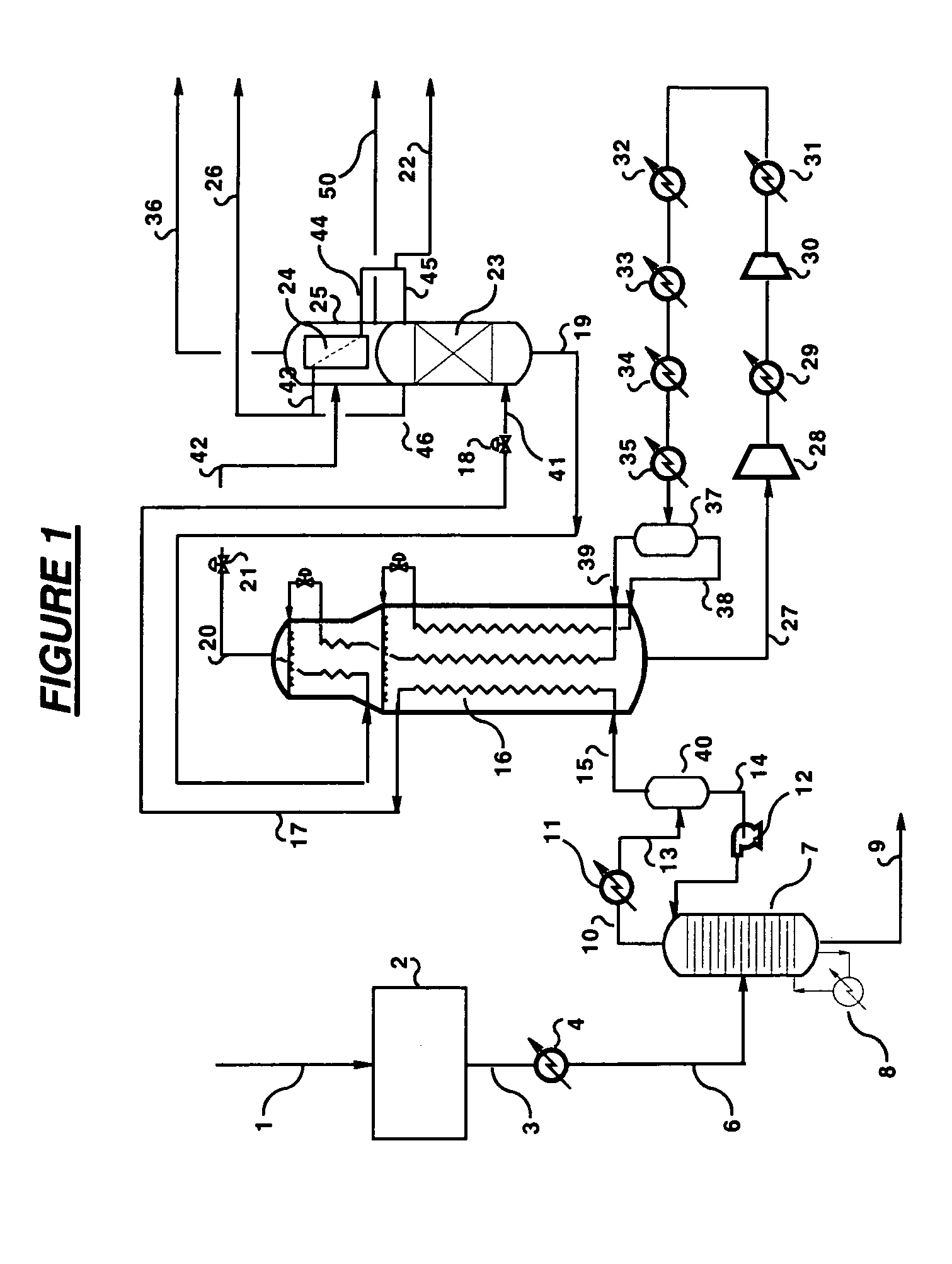
[0090]This Example is based on the embodiment of FIG. 1. The LNG process is supplied with 88,000 lbmol / h (40,000 kgmol / h) feed natural gas at ambient temperature and 900 psia (6.2 MPa) pressure containing 4.8 mol % nitrogen, the balance being mainly methane. The feed gas is dried and precooled and pretreated in separation column 7 such that it enters heat exchanger 16 at a temperature of −38° F. (−39° C.) and a pressure of about 850 psia (5.8 MPa). Stream 17 leaves heat exchanger 16 at a temperature of −178° F. (−116.5° C.) and is let down in pressure to 220 psia (1.5 MPa) before feed to nitrogen-rejection column 23, which operates at 220 psia (1.5 MPa). Stream 19 is withdrawn from the bottom of the column 23 and is further cooled to −247° F. (−155° C.) in heat exchanger 16. Stream 20 leaving the heat exchanger 16 is then let down to low pressure into flash drum 25. Product LNG stream 50 is withdrawn from flash drum 25 at a temperature of −261° F. (−163° C.) with a nitrogen content ...

example 2

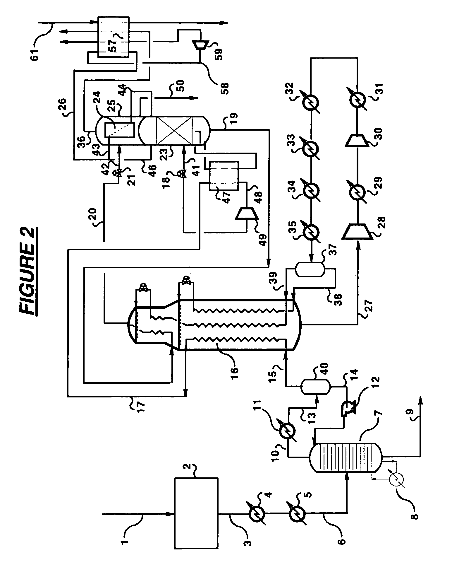
[0091]This Example is based on the embodiment of FIG. 1 with the enhancement of crude helium extraction of FIG. 5. The LNG process is supplied with 88,000 lbmol / h (40,000 kgmol / h) feed natural gas at ambient temperature and 900 psia (6.2 MPa) pressure containing 4.8 mol % nitrogen and 600 ppmv helium, the balance being mainly methane. The feed gas is dried and precooled and pretreated in separation column 7 such that it enters heat exchanger 16 at a temperature of −38° F. (−39° C.) and pressure of about 850 psia (5.9 MPa). Stream 17 leaves heat exchanger 16 at a temperature of −178° F. (−116.5° C.) and is let down in pressure to 220 psia (1.5 MPa) before feed to nitrogen column 23, which operates at 220 psia (1.5 MPa). Stream 19 is withdrawn from the bottom of the column 23 and is further cooled to −247° F. (−155° C.) in heat exchanger 16. Stream 20 leaving the heat exchanger 16 is then let down to low pressure into flash drum 25. Product LNG stream 50 is withdrawn from flash drum 2...


PUM


Abstract

Nitrogen is removed from a liquefied natural gas feed (41) by a two stage separation in which the liquefied natural gas (41) is first fractionated (23) to provide a first nitrogen-enriched overhead vapour stream (46) and a nitrogen-containing bottoms liquid stream (19) and then at least a portion of said bottoms liquid stream (19) is fractionated (25) to provide a second nitrogen-enriched overhead vapour stream (36) that is of lower purity than said first overhead vapour stream (46) and a purified liquefied natural gas stream (50). The first fractionation is conducted in a distillation column (23) refluxed (45) with nitrogen overhead (43) condensed in a condenser (24) located in a flash drum (25) in which the second fractionation is conducted. The second nitrogen-enriched overhead vapour stream (36) provides fuel gas for use in the natural gas liquefaction plant.

Description

BACKROUND OF THE INVENTION[0001]The present invention relates to the removal of nitrogen from liquefied natural gas (LNG) streams and use of only part of the nitrogen content in fuel gas whilst the remaining nitrogen content can be vented to atmosphere. There is provided a method in which the nitrogen is removed in two stages at different concentrations and corresponding apparatus for natural gas liquefaction to provide a nitrogen-freed LNG product.[0002]Gas turbines are usually used to provide the shaft work and electrical power for LNG facilities. Fuel for these gas turbines is often generated as off-gasses from the LNG process. In a conventional LNG process, nitrogen present in the feed gas is normally rejected into this fuel gas stream. However, more environmentally friendly low nitrogen oxide (NOX) burners for these turbines have a lower tolerance for nitrogen in the fuel gas than previously used burners. Accordingly, in some plant locations with high nitrogen containing feed g...

Claims


Application Information

Patent Timeline
Patent Type & Authority Patents(United States)
IPC IPC(8): F25J3/00
CPCF25J1/0015F25J1/0022F25J1/0037F25J1/0042F25J1/0052F25J1/0055F25J1/0072F25J1/0214F25J1/0216F25J1/0218F25J1/023F25J1/0264F25J1/0267F25J1/0283F25J1/0292F25J3/0209F25J3/0233F25J3/0257F25J3/029F25J2200/02F25J2200/50F25J2200/72F25J2205/02F25J2210/06F25J2220/64F25J2240/30F25J2270/04F25J2215/04F25J1/0238Y10S62/927F25J1/02F25J3/02
Inventor SPILSBURY, CHRISTOPHER GEOFFREY
Owner AIR PROD & CHEM INC
Why Eureka
Try Eureka